Bonfiglioli EM-ENC-03 Expansion Module
Module positioning: Lower level slot option for frequency converter, integrated with EM-SYS Bangfeili private CAN system bus and second incremental encoder (speed sensor) input. Compare EM-ENC-02: EM-ENC-02 comes with additional AI/AO, DI/DO, PTC; EM-ENC-03 only retains the CAN system bus and the second incremental encoder, without analog IO, digital IO, or PTC interfaces.
Security and Document Fundamentals
Safety Specifications
The disassembly and assembly module must be completely powered off and wait for the DC bus capacitor to fully discharge; ESD electrostatic protection, prohibit touching the components on the back of the PCB; Only licensed electricians are allowed to operate.
Storage without power for up to 1 year; Terminals are prohibited from being plugged in or unplugged while live.
This manual is a supplementary manual and needs to be used in conjunction with the ACT/ACU machine operation manual.
Module Hardware Resource List
This module does not have analog input, analog output, DI/DO, PTC temperature detection.
EM-SYS CAN high-speed system bus (ISO 11898, up to 1Mbaud)
EM-ENC second incremental encoder/speed sensor input (A+/A -, B+/B -, maximum input frequency 300kHz)
Terminal: Pluggable Wieland connectors X410A and X410B, with a tightening torque of 0.2-0.3Nm.
Mechanical and Electrical Installation
Mechanical installation: Remove the lower cover plate of the frequency converter when powered off, insert the module into the dedicated slot on the lower level, and restore the cover plate; It is strictly prohibited to disassemble or assemble with electricity.
X410A terminal (encoder interface)
Terminal signal description
1 A+Encoder Phase A+
2 A Encoder Phase A
3 B+Encoder B Phase+
4 B-Encoder B-Phase
5 NC vacant
6 GND signal ground
7 NC vacant
X410B terminal (CAN system bus)
Terminal signal description
1-4 NC vacant
5 CAN‑Low CAN‑L
6 CAN‑High CAN‑H
7 GND CAN signal ground
Dial switch S1/S2/S3
Rules for setting dialing purposes
S1/S2 CAN bus terminal S1=ON, S2=OFF: Passive terminal (recommended); S1&S2 are both ON: active terminals; Open the terminal at the beginning and end nodes of the bus, and turn off all nodes in the middle; Only one active terminal is allowed on the entire bus; All factory products are turned off
S3 encoder 150 Ω terminal resistance only 5V differential RS-422 encoder opens S3=ON; The 24V HTL single ended encoder S3 must be turned off, otherwise the hardware will be damaged
Cable requirements: CAN bus must use twisted pair shielded cables, with PE extensively connected at both ends of the shielding layer; power cables and communication cables must be physically separated and routed.
EM-SYS system bus CAN interface
The CAN system bus logic is completely consistent with EM-SYS and EM-ENC-02; When the CM-CAN module is inserted into Slot-B, the CAN bus is taken over by CM-CAN, and the CAN function of this module is disabled, but the encoder function is not affected.
Core bus parameters
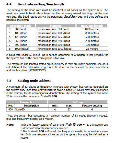
Parameter 900 Node ID: -1 disabled (factory); 0=System Bus Master Station; 1-63=slave station; A single bus can have a maximum of 1 master station and 63 slave stations.
Parameter 903 Baud Rate: The baud rate of all nodes must be consistent.
Maximum cable length for baud rate
50kBaud 1000m
100kBaud 800m
125kBaud 500m
250kBaud 250m
500kBaud 100m
1000kBaud 25m
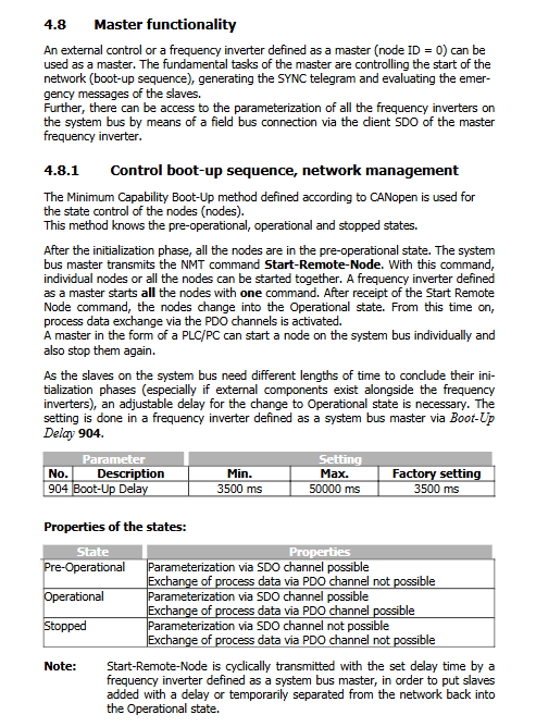
Three working states of the network
Pre Operational: SDO parameter read and write available; PDO process data does not work, default state when powered on.
Operational operation: SDO and PDO are all available, and data exchange process is normal.
Stopped: SDO and PDO are all disabled.
Master master station capability (Node-ID=0)
NMT network management, controlling the start and stop of all nodes; Parameter 904 Boot Up Delay: Power on startup delay of 3500-50000ms.
Generate SYNC synchronization message for multi axis synchronous PDO sampling; Parameters 918 SYNC Identifier, 919 SYNC Time.
Receive Emergency fault messages from slave stations; Parameter 989 Emergency Reaction: 0=Main Station Shutdown Report F21nn; 1=Only alarm without stopping the machine.
Gateway transparent transmission: The local Profibus DP/CM-232-485 serial port can directly access the parameters of all slave stations on the CAN bus, without the need for PLC to directly connect to CAN hardware.
SDO Service Data Object (Parameter Read Write)
SDO1 is used for PLC/master station access parameters; SDO2 reserves visual debugging tools.
Expedited fast transmission; Support int/uunt/long; The string parameter is inaccessible.
Index=frequency converter parameter number, Sub Index=dataset number; Write dataset 0-4 to EEPROM; 5-9 RAM only, avoiding EEPROM erase life loss.
Gateway transparent transmission rule: Fill in the target CAN slave Node ID in byte 3 of Profibus DP PKW; Fill in the Node ID in the VABus serial port packet header.
PDO Process Data Object+Virtual Links (Core)
TxPDO: Fill in the internal source number Source Number of the local machine, and map the local control word, frequency, IO, etc. to the sent message.
RxPDO: Receive messages and generate new source numbers (700-729), which are directly referenced by the internal function inputs of the drive.
8-byte payload supports mixing: Bool (2 bytes)/Word (2 bytes)/Long (4 bytes).
Each driver has 3 sets of RxPDO/TxPDO, with a fixed 8-byte payload for each set.
PDO triggering mode: time triggered/SYNC synchronous triggered; Support RxPDO and SYNC timeout monitoring.
Fault: F2200 SYNC timeout; F2201-03 RxPDO1-3 timeout; F2210 CAN Bus OFF bus is turned off.
Virtual Links: Direct data exchange between frequency converters without the need for upper level PLC transfer
Bus load planning: The official Load_Systembus.xls tool is provided, and it is recommended that the total bus load be ≤ 80%. If it exceeds 90%, the system is unreliable.
Parameter access restriction: PDO mapping and virtual link related parameters KP500 operation panel are not visible and can only be modified by importing XPI configuration files into VPlus software; The bus status monitoring parameters can be read from the VAL menu.
Parameter 978 Node State node status; 979 CAN State physical layer bus status (OKAY/WARNING/BUS OFF).
Second incremental encoder EM-ENC function
This is the exclusive hardware of EM-ENC-03, serving as the second speed sensor for the driver.
Hardware Specifications
Maximum input frequency: 300kHz; Supports 5V RS-422 push-pull differential and 24V single ended HTL signal.
S3 DIP: Only the 5V differential encoder activates the 150 Ω terminal resistor; Always turn off S3 for 24V HTL.
key parameters
Parameter Number Parameter Name Description
493 Operation mode speed sensor 2 0 is turned off; 4 times the fourth harmonic; 104 fourth harmonic inversion (equivalent to swapping A/B phase)
494 Division Marks Speed Sensor2 Encoder Line Count, Range 1-8192
495 Level 0=5V push-pull; 2=24V single ended
766 Actual Speed Source Speed loop actual feedback source: 1=motherboard native encoder; 2=EM-ENC second encoder in this module
Monitor actual value parameters
219 Frequency speed sensor2: Second encoder frequency Hz
220 Speed, speed sensor 2: Second encoder speed rpm
Functional purpose
Can be used as an actual feedback source for speed closed-loop, with parameter 766 switching;
Can be used as a frequency/percentage given source;
Can be used for actual value comparison and overspeed detection;
Encoder related fault codes
F14-30: Encoder signal fault;
F14-31: Missing one phase signal;
F14-32: Phase sequence direction error.
Parameter List and Fault Overview
VAL actual menu (readable by KP500): Encoder 2 frequency, speed, bus Node State, CAN State.
PARA parameter menu: encoder configuration all parameters, system bus complete set of configuration parameters; PDO mapping parameter KP500 is not visible, VPlus+XPI file access.
Fault Classification
Encoder hardware failure: F14-30/31/32;
System bus fault: F21xx slave station fault; F22 series SYNC/RXPDO timeout BUS‑OFF。