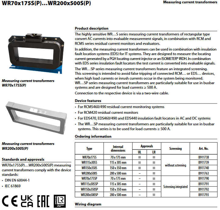
BENDER WR70 × 175S (P)~WR200 × 500S (P) rectangular measuring current transformer
Product classification and core differences
WR… S: Standard transformers have no built-in shielding and are used in conventional cable circuits.
WR… SP: With integrated shielding layer version, the shielding layer suppresses interference caused by high load current and closing surge current, specifically used for busbar systems with load current ≥ 500A, to avoid RCM and EDS equipment misoperation.
List of compatible host devices
Residual current monitoring: RCMS460/RCMS490, RCM420;
IT system insulation fault location: EDS440, EDS460, EDS470, EDS490, in conjunction with the IRDH series ISOMETER insulation monitoring host; Receive positioning pulse signals from IRDH or PGH injectors.
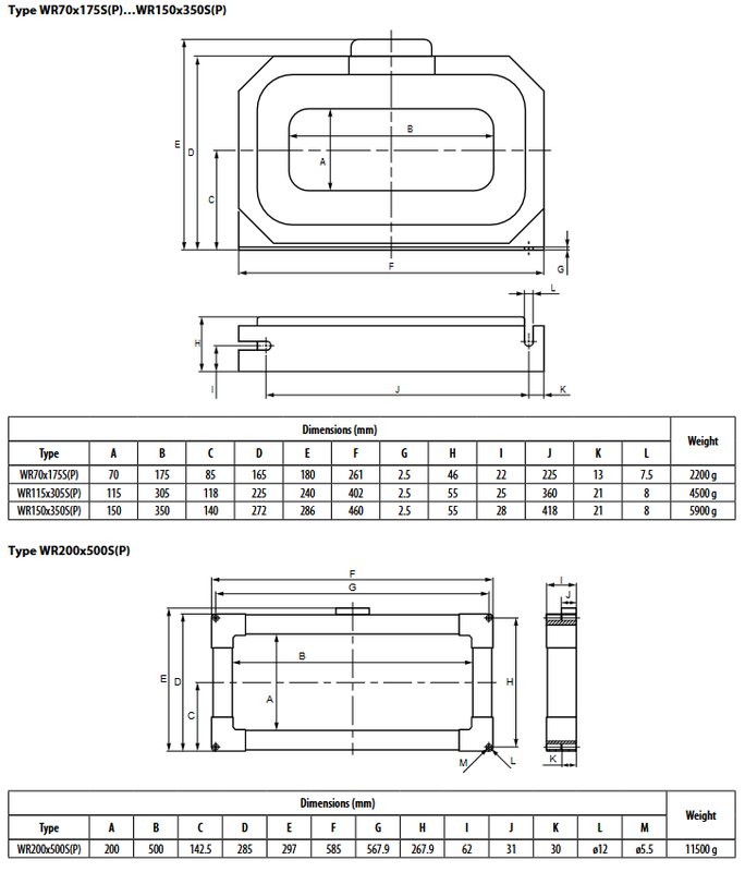
Model, external dimensions, and weight
Window A (height) × B (width); All are rectangular through windows, suitable for busbar and multiple large cables to pass through.
Model Window A × B (mm) Whole Machine Weight
WR70×175S(P) 70 × 175 2200 g
WR115×305S(P) 115 × 305 4500 g
WR150×350S(P) 150 × 350 5900 g
WR200×500S(P) 200 × 500 11500 g
WR70 × 175~WR150 × 350S (P): Universal shell installation;
WR200 × 500S (P): Large independent window structure with M12 mounting holes.
Key electrical technical parameters
Item | Parameter
Implement standards DIN-EN 60044-1 and IEC 61869
Maximum system voltage Um AC 720 V
Rated impulse withstand voltage 3 kV
Transformation ratio 600/1
Rated load 180 Ω
Nominal capacity 50 mVA
Frequency range 50-400 Hz
Internal secondary resistance 5-8 Ω
Accuracy level 5 (for signal measurement, non metrological)
Secondary protection with built-in P6KE6V8CP suppression diode and secondary side overvoltage protection
One continuous thermal current of 100 A
Short time thermal withstand current 14 kA/1 s
Dynamic stable current 35 kA/30 ms
The minimum measurable current at once is ≥ 10 mA (suitable for EDS weak positioning pulse)
Secondary wiring cable length requirements (S1/S2 connected to controller)
Ordinary single core 0.75 mm ²: maximum 1 mm;
Twisted pair cable ≥ 0.75 mm ²: maximum 10 mm;
Shielded cable J-Y (St) Y ≥ 2 × 0.6mm ² (recommended, shielded single end PE): maximum 40 m.
Environmental and mechanical conditions
Working temperature: -10~+55 ℃; Storage -40~+70 ℃; Climate level 3K22;
The impact vibration meets the IEC 60068 series;
Protection: Internal IP40; Wiring terminal IP20;
Flame retardant grade UL94-V0; Any installation posture; Fix with screw M5;
Secondary terminal: screw terminal, wire section 0.2-4 mm ² hard wire/0.2-2.5 mm ² flexible wire.
Mandatory rules for wiring and installation (emphasis)
Wiring diagram
Primary side: All charged conductors L1/L2/L3/N pass through the transformer window; PE protection wires are strictly prohibited from passing through transformers. Secondary side: S1 (K) and S2 (L) are connected to RCM/RCMS/EDS equipment. P1 (K) and P2 (L) markers define the direction of threading once.
Installation prohibitions and requirements
PE ground wire is absolutely prohibited from passing through the transformer window; Prohibit shielded cables from passing through transformers; Prohibit low impedance conductor loops from passing through windows.
All current carrying phase lines and neutral line N must pass through the transformer in the same direction; The principle of residual current: vector sum is the leakage current.
The cable insertion should be aligned with the center of the transformer window; The bending position of the cable should be at least twice the height of the transformer (90 ° bending), meeting the minimum bending radius.
The SP shielding model is used for ≥ 500A busbars to reduce false alarms caused by high loads and surge currents.
Shielded cables must be used for long-distance secondary cables, with the shielding layer connected to the protective grounding PE at one end and not grounded at both ends.
Application Description
TN-TT grounding system: matched with RCM/RCMS residual current monitor to collect residual leakage of the system;
IT ungrounded system: in conjunction with EDS46-49 series fault location unit+IRDH575 insulation monitoring host; Pick up weak positioning test pulses output by the host to achieve branch circuit grounding fault location;
The WR-SP shielded version is preferred for high current busbar cabinets to suppress electromagnetic interference caused by high loads and startup shocks, and prevent EDS/RCM misoperation.