Jenaer Antriebstechnik ECOVARIO ® Installation and Operation Instructions for 114/214/414 Servo Drivers
Technical specifications, ordering codes, and compatible motors
Power level specifications
Model power supply output capability
ECOVARIO 114 AC:20‑48VAC; DC24-70VDC peak current of 14A, built-in small braking resistor
ECOVARIO 214 AC:20‑120VAC; DC24-170VDC peak current of 14A, without built-in braking resistor, requires external connection
ECOVARIO 414 AC: 20-265VAC (single-phase/three-phase); DC48-360VDC peak current of 14A, without built-in braking resistor, requires external connection
The peak current duration of all models is 5 seconds; if the radiator temperature exceeds 70 ℃, the output will be linearly reduced; Drive hardware overheating protection shutdown at over 90 ℃.
Environmental conditions: Operating temperature 5-40 ℃, humidity 5-85%, no condensation; Protection level IP20; Vertical DIN rail installation; Altitude ≤ 1000m without capacity reduction.
Overall dimensions:
114:42 mm (width) × 279 mm (height) × 167 mm (depth), weight 1.35 kg
214/414:62 mm (width) × 279 mm (height) × 167 mm (depth), weight 2.1 kg
Order coding rules
ECOVARIO ® Segment meaning: 1) Voltage level (1=100V, 2=200V, 4=400V DC bus) 2) Current level: 14 represents maximum 14 A (5-second peak) 3) Power supply type: A (AC/DC); B (DC only); R=with STO safety torque cut-off; N=No STO 4) Bus selection: CANopen/Profibus DP V0/EtherCAT/Ethernet/RS232/RS485 multiple combinations 5) Certification: A=CE; J=CE+UL; K=CE+UL special version 6) parameter set number; Firmware version number.
Example: ECOVARIO ® 414 AR-AA-000-000: 400V busbar, 14A, AC/DC power supply, with STO; CAN+RS485+encoder simulation output, CE standard model.
Support motor types
ECOSPEED: Two phase and three-phase synchronous rotary servo motors;
ECOSTEP: Two phase encoder reversing stepper servo motor;
ECOLIN series direct linear motor (iron core/no iron core);
DC servo motors (brushed, brushless BLDC), when using DC motors, it is necessary to contact the manufacturer’s technical support;
Does not support rotary transformers, only encoder feedback can be used; Supports incremental, SIN-COS, HIPERFACE, BiSS-C absolute value encoders.
Mechanical and Electrical Installation
Key points of mechanical installation
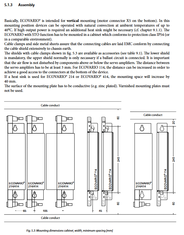
Must be installed vertically, with motor connector X5 facing downwards; Natural convection heat dissipation; It is recommended to choose external heat sink DPX10 for high-power working conditions.
The installation of the bottom plate must be made of conductive galvanized steel plate, and it is prohibited to spray paint the insulated bottom plate; Ensure high-frequency grounding of the casing;
The minimum distance between drives should be ≥ 3mm; the cabinet protection level of models with STO function should be at least IP54;
The cable shielding must use the original shielding kit and be crimped to the cabinet ground in a 360 degree area;
Reserve ventilation space around the perimeter, and ensure that the upper and lower ventilation channels are not obstructed by cables or devices.
Key requirements for electrical installation
All wiring operations must be completely powered off and locked to prevent accidental power on;
PE protection ground wire cross-sectional area ≥ power line cross-sectional area; Two grounding methods: shell grounding column; Alternatively, the power terminal X6 can have independent PE.
EMC compliance mandatory requirement: All motors, encoders, and buses must use shielded cables; Separate the routing of power cables and control signal lines; Add absorption circuits to contactors and relays;
Fuse selection: 10A slow melting fuses are recommended for both AC and DC circuits; UL application fuses must comply with UL489/RK5 category.
Power supply note: ECOVARIO414 cannot be directly connected to 400V three-phase mains power and must be isolated from transformers/autotransformers; The maximum AC input for the 114 model is 48VAC.
DC bus X4 terminal: can be connected to external braking resistors or directly supplied with external DC power; The DC powered version of the driver does not have internal power on surge current limiting, and external power sources must add surge current limiting circuits.
Long cable reminder: If the motor cable is greater than 25m, the cable capacitance will increase the leakage current and reduce the performance of the driver.
Detailed definition of all interfaces
Interface distribution: digital IO, analog, power terminal, encoder A/B, RS232/RS485, USB debugging port CANopen、 Optional X22 (EtherCAT/Profibus DP V0/Ethernet/Encoder Simulation) and STO secure interface.
Control signal interface
X1 (24V digital input/output, all models)
3 digital outputs (maximum single 0.5A, total output 1A) READY, OUT1, OUT2;
Two digital inputs: ENABLE enabled, RESET reset; External 24VDC power supply.
X2 digital input
214/414: Limit positive and negative, return to zero switch, universal DI;
114 model: DI, when configured with R (STO version), X2 multiplexing is used as the STO safety input/output signal ASI/ASO1/ASO2.
X3 analog quantity (only available in 214/414, 114 does not have an independent X3): 2-channel differential analog input -10~+10V; 2-channel analog monitoring output MON1/MON2, ± 15V power supply to external potentiometer.
X4 DC bus&braking resistor: connected to external braking resistor or external DC power supply; ⚠️ Up to 400VDC high voltage. The threshold for opening and closing the braking resistor can be modified through the object dictionary software.
X5 motor power terminal: compatible with two-phase, three-phase, DC motors, U/V/W phase; PE protection grounding.
X6 main power input: distinguish between 114, 214, and 414 pin definitions. Internally, there is a current limiting thermistor for power on impact; The interval between two power ups should be ≥ 10s; it is prohibited to use contactors for high-frequency cycling to turn on and off the power supply of the driver.
X7 brake output terminal: motor holds brake; Continuous maximum 0.5A, peak 1A; high current holding brake requires external relay.
X8 (only for 214-R/414-R models) STO safety interface: ASI safety input, ASO status feedback relay contact. The STO signal of the 114-R model is multiplexed on X2.
encoder interface
X11 Encoder A: 5V encoder power supply; Supports TTL increment, 1Vpp sine and cosine encoders, with a maximum cable length of 50m;
X12 Encoder B: Supports incremental, SIN-COS, HIPERFACE, BiSS absolute value encoders; The power supply voltage of the encoder can be set to 5-14V through an external resistor.
Serial and bus interface
X13 RS485/RS232: 214/414 comes with two high-speed capture inputs CAP1/CAP2 for event timestamp capture; RS485 supports multi-point bus, up to 32 stations;
X14 USB debugging port (Type-B): Connect to a PC to run ECO Studio software, set parameters, and download firmware; The drive device ID must be unique;
X21 CANopen interface, following CiA-DS301 and DSP-402 driver specifications; A 120 Ω terminal resistor is required at both ends of the bus; The maximum baud rate is 1Mbit/s; The later version of the hardware CAN interface does not require external power supply.
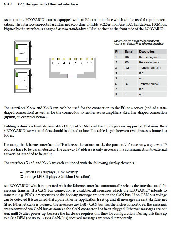
X22 optional multifunctional interface (hardware selected when ordering, hardware cannot be changed later): choose one from four
Encoder simulation output;
Profibus‑DP‑V0;
100M Fast Ethernet;
EtherCAT。
STO safety torque shutdown function
The hardware version suffix with R is required to have STO function: 114-R, 214-R, 414-R.
Dual channel safety architecture: Channel A safety relay cuts off the power level gate power supply; Channel B enables input and cuts off power output through Enable and CPLD. Single channel failure, while the other channel remains in a safe state.
Performance parameters: SIL2, PLd; PFH=1.26E‑09/h; STO only cuts off the motor torque output and will not disconnect the high voltage of the DC bus!
Use hard constraints
STO activation is recommended to be triggered after the motor has completely stopped;
There is a vertical suspended load, and in addition to STO, an additional mechanical brake must be applied for mechanical locking. STO cannot prevent gravity from falling;
STO is strictly prohibited as an emergency stop, maintenance power outage, or long-term shutdown method!
Status feedback: ASO relay dry contact, output STO activation status, can be connected to the upper safety PLC.
Testing requirements: The STO function must be fully tested for machine manufacturing, hardware modifications, wiring modifications, and firmware updates; Perform a complete safety function verification at least once a year under normal operating conditions; Related fault code D00 (restart lock), D01 has no external enable.
Debugging and commissioning
Pre power on checklist: grounding, shielding, wiring, brake, braking resistor, encoder wiring; Confirm that there is no short circuit.
Driver panel: Status LED digital display, displaying status codes and fault codes; The panel buttons can set the bus station ID.
Fault diagnosis: Alarm code starting with D; Distinguish between hardware faults, communication faults, safety STO faults, and overcurrent, overvoltage, and overheating.
Debugging software: ECO Studio PC software (Windows), USB/Ethernet/CAN can be connected; Used for parameter configuration, oscilloscope, firmware upgrade; Supporting document “Object Dictionary Manual”.
Accessories, braking resistors, cables
Accessories list: heat sink DPX10; Shielding kit; VARIOSSWITCH operating unit; USB boot kit, CAN boot kit; Complete set of plug connectors;
Braking resistor DPR series: distinguish between 100W/200W/250W/500W cooling type; 114 has a built-in low-power braking resistor, but external connections are still required for high-power operating conditions; The resistance value must strictly match the driver model;
Cables: motor cables, encoder cables, bus shielded cables, original factory models such as MOT xxx, INK xxx, ABS xxx.