EXOR UniOP ePALM10 Handheld HMI
Main highlights and functional features
hardware configuration
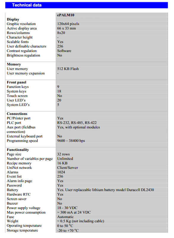
Display screen: 120 × 64 pixel semi reflective LCD, 8 lines × 20 characters; Software adjusts contrast without brightness adjustment; Supports scalable fonts and 256 custom characters.
Keyboard: 27 keys with tactile feedback; 9 function keys F1-F9+18 system keys; No touch screen.
LED: 20 user LEDs, 5 system status LEDs.
Storage: 512KB Flash user program memory; Formula storage 16KB; up to 1024 alarms and 256 event histories.
RTC real-time clock: backed up by a replaceable lithium battery DL2430 (Duracell); Battery failure will result in loss of RTC, event, and recipe data.
Password: Level 8 password permission; Support keyboard macro editor; The report can be output to a serial printer.
UniNet: Supports Client/Server network mode.
Security hardware (hard wired, not through software):
Emergency Stop E-Stop: Two normally closed NC hardware contacts;
Dead man dual hand enable button: left and right independent normally open NO hardware contacts.
Software development: programming software UniOP Designer V5.08; Supports 130+types of industrial PLC drivers; Digital/text/bar chart dynamic graphic objects.
Physical protection: IP65; Weight approximately 0.5 kg (excluding cables); The shell is impact resistant and suitable for handheld use in the workshop.
Electrical and Environmental Specifications
Project parameters
Power supply 18-30 VDC, typical 24VDC
Approximately 300 mA at 24V power consumption
Insurance self recovery insurance
Working temperature: 0-50 ℃; Storage -20~+70 ℃
Humidity 5-95% RH, no condensation
EMC EN61000-6-4 (emission), EN61000-6-2 (anti-interference)
The circuit level of the whole machine (emergency stop, enable all circuits) belongs to SELV safety ultra-low voltage and must comply with EN60950, with a maximum not exceeding 48VDC
The supporting cable diameter and outer diameter of the cable are 7-11 mm; the standard cable contains multiple signal wires inside, with emergency stop cable of 1 mm ² and ordinary signal of 0.14-0.35 mm ²
Overall dimensions: 116 mm x 86 mm x 239 mm.
Interfaces, terminals, and cables (CA01 interface board, detachable 5 sets of terminals CN1~CN5)
CN1 Aux Port: Used for optional TCM fieldbus module.
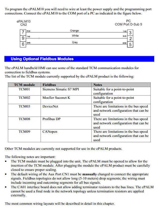
CN2 PC/Printer port: programming, connecting to serial printer; Contains TXD/RXD/RTS/CTS,+5V (maximum 100mA output).
CN3 PLC Port:RS232/RS422/RS485; CHA ± CHB -, can also output+ 5V@100mA .
CN4 Power supply:+24VDC, Common, PE protection ground.
CN5 additional signal: Left and right Dead man enable, 4-channel NO normally open contacts.
Key point: The emergency stop E-Stop does not go through the terminal on the board and is directly hard wired inside the cable.
Standard cable model
EPALM10-0061:5 meter cable;
EPALM10-0062:10 meter cable; The cable end has no connector and needs to be manually crimped inside the control cabinet; The cable must be equipped with a magnetic ferrite ring provided with the goods to ensure EMC performance.
Cable color definition
Power supply:+24V red, Common black;
PC/print port, PLC communication port: multi-color thin signal line;
Dead man enable: 0.35 mm ² for cyan, blue black, etc;
Emergency stop two NC lines: green, yellow, brown, orange, 1 mm ² thick line; SELV circuit, it is strictly prohibited to connect more than 48V.
Attention to RS485/422 usage: Unused RXD is grounded, CTS is grounded+5V, and floating is prohibited. If you want to use the Aux expansion port, you need to manually transfer the signal line of the PLC port to the CN1 terminal.
Optional TCM fieldbus module (installation precautions)
Does not support TCM04, TCM07, TCM10; Support List:
|Module model | Bus type | Remarks|
|TCM01 | S7-MPI | Point to Point|
|TCM02 | Suconet-K | Point to point|
|TCM03 | DeviceNet | Bus speed and topology have limitations|
|TCM08 | Profibus DP | Bus speed and topology have limitations|
|TCM09 | CANopen | Bus speed and topology have limitations|
Installation constraints:
Need to disassemble the entire machine casing and insert the TCM module; After assembly, the casing must be restored to ensure an IP65 seal.
The local hardware board cannot integrate terminal resistors; If the handheld device is the last node of the bus, an external terminal resistor must be added.
Handheld cables 5-10 meters in length belong to long branches, and the fieldbus topology does not allow it. It is necessary to install dual line wiring inside the cabinet.
Panel LED status indication
Red LED: constantly on=hardware failure; Flashing=low battery voltage.
Green button feedback LED: Press the button to light up.
Green running LED: the device is running normally; Flashing=communication failure.
Red alarm LED: constantly on, there is an active alarm; Flashing=Alarm requires confirmation.
Green system LED: Recipe/event backup in progress.
The F1-F9 button LED and numeric button LED can be controlled through RDA bit macro programming.
Battery replacement process (DL2430 lithium battery)
Replacing the battery will result in loss of RTC clock, event history, and recipe data.
Disconnect the external power supply of the device;
Unscrew the 6 screws from the casing to open it;
Remove the old battery from the CPU board and replace it with a new DL2430;
Close the casing and tighten the 6 screws; Power on and confirm that the battery is in normal condition.
Ordering and Accessories
Ontology
EPALM10-0061:5 meter cable;
EPALM10-0062:10 meter cable.
Hanging hook accessories:
AHOOK01: Non magnetic wall hanging hook;
AHOOK02: Hook with magnetic attraction.
Key engineering precautions
Emergency stop and Dead man are hardware hard wired, do not follow software logic, all circuits belong to SELV, voltage ≤ 48VDC; The internal wiring of versions after 2001-10 has been revised, and old drawings cannot be directly applied.
It is necessary to use cables with ferrite magnetic rings to ensure EMC.
In fieldbus mode, the machine does not have built-in terminal resistors, and the bus terminals must be externally connected; Handheld cables with a length of 5-10 meters cannot be directly used as bus branches, and the control cabinet side has been changed to input/output dual lines.
Replace the lithium battery, the formula, event records, and clock are all lost, backup in advance.
Not supporting current loop 20mA interface; Some TCM modules are unavailable.
IP65 protection, after disassembling the casing and installing the TCM module, the seal must be fully restored.