Rockwell PowerFlex 700 AC frequency converter
Product Overview
1. Core control mode
V/Hz voltage frequency ratio: simple applications such as fans and water pumps;
Sensorless Vector: wide speed range and high torque output;
Equipped with encoder closed-loop vector control (patented Force Technology), achieving low-speed/zero speed full torque.
Open loop speed adjustment accuracy ≥ 0.5%; The feedback of the closed-loop encoder can reach 0.001% of the base speed;
Open loop torque adjustment ± 5%; Closed loop torque regulation ± 2%, supporting zero speed load holding.
2. Built in functions
Flying Start: Directly connected to the rotating motor, no speed feedback required;
Inertia Ride Through: Relying on the rotational energy of a large inertia load to withstand short-term power outages and avoid downtime;
TorqProve brake torque verification: the combination of frequency converter and mechanical brake, for lifting equipment;
16 step position index/velocity contour; Built in PI process regulator;
Active current limiting and bus voltage regulation to reduce tripping; Two independent acceleration and deceleration times can be set;
Overload capacity: 110% overload lasts for 60 seconds, 150% overload lasts for 3 seconds.
3. Hardware and packaging
Type of shell protection
IP20/NEMA-1: Installation inside the cabinet;
IP54 NEMA-12 independent wall mounted: only Frame5-6, power 75-200Hp;
IP54 flange installation: The radiator faces outward, and the front of the cabinet is IP00. The radiator dissipates heat outward;
Zero Stacking: Frame0-6 frequency converters can be installed closely side by side, without derating in an environment of 50 ℃. They can be disassembled and assembled in a bookshelf style, and single maintenance does not affect adjacent equipment;
Conformal Coating: Resistant to moisture, mold, dust, and corrosive gases;
Built in components: integrated EMC filter, common mode choke coil; Built in braking IGBT (standard for Frame0-3, optional for 4-6); ≤ 25Hp models can have built-in braking resistors;
Human computer interface HIM: 7-line x 21 character backlit LCD, multilingual; Support local handheld and panel remote installation; PC software Connected Components Workbench is used for configuration and debugging.
4. Communication capability (DPI adapter)
Support: EtherNet/IP、ControlNet、DeviceNet、Profibus‑DP、Modbus‑RTU/TCP、BACnet、CANopen、DF1‑RS485。 Function: Adapter routing, ADR device automatic replacement, Peer Control master-slave control, COS message for status changes, custom actions for network failures.
5. Model coding rules
Model 20B-xxxx-xxxx: including voltage level, current power, frame, brake, shell HIM、 Feedback card, communication slot, control board (Standard/Vector), special firmware.
Voltage codes: B (240VAC), C (400VAC), D (480VAC), E (600VAC), F (690VAC); H/J/N/P/R/T/W correspond to different DC bus voltages. The Frame7-8-9-10 model has been discontinued from sale.
Certification, Environmental and Electrical Specifications
1. Product certification
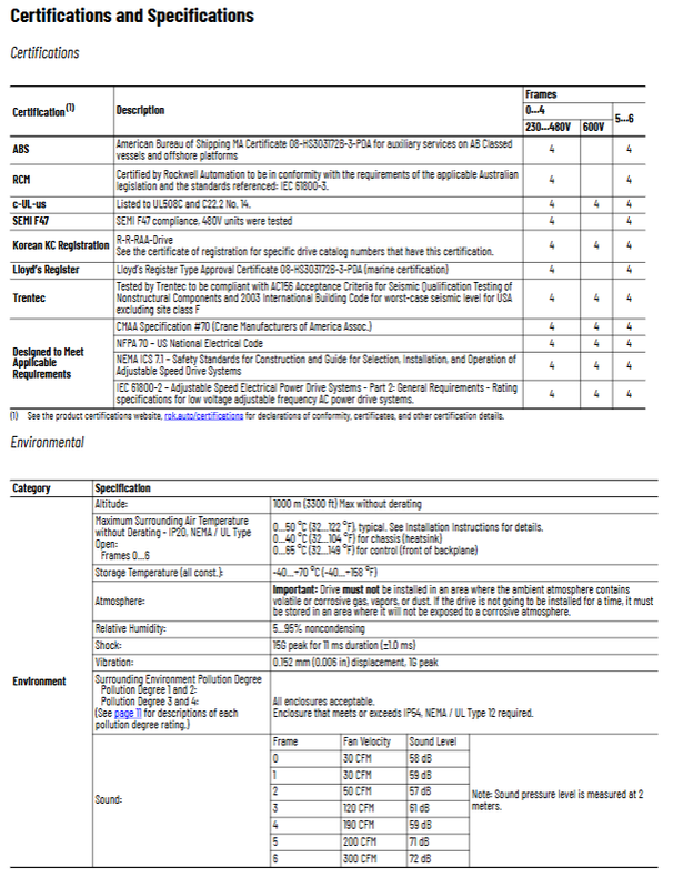
c‑UL‑us、RCM、KC、ABS、 Lloyd’s Register, SEMI-F47 earthquake certification; Meet CMAA crane specifications; Compliant with NEC and IEC61800-2; The new version of the document has removed the CE declaration.
2. Environmental conditions
Altitude: ≤ 1000m without derating; Higher than 1000m requires current reduction;
Ambient temperature
IP20 (NEMA1):0‑40℃; Removing the top label can reach 0-50 ℃;
IP54 independent wall mounted 0-40 ℃; The flange installation radiator side is 0-40 ℃, and the front of the cabinet is 0-55 ℃;
Storage temperature -40~+70 ℃; Humidity 5-95% without condensation; Pollution level 1/2; Pollution level 3-4 must have an IP54 enclosure;
Vibration impact and noise pressure provide the noise values of each frame fan.
3. Electrical protection threshold
Including input overvoltage, undervoltage, DC bus overvoltage/undervoltage, radiator overheating, hardware/software overcurrent, ground fault, output short circuit; Surge withstand 6000V; logic anti-interference 1500V arc interference.
Short term power supply maintenance: full load for 15ms; logic control maintenance for a minimum of 0.5s, typically 2s.
Displacement power factor 0.98; The rated operating efficiency is 97.5%.
PWM carrier: 2, 4, 8, 10 kHz; Factory default 4 kHz; Carrier increase requires derating; Output frequency standard 0-400Hz, vector mode 0-420Hz.
Motor matching suggestion: The power ratio between the frequency converter and the motor should be a minimum of 1:2 and a maximum of 2:1.
4. Input power form
Complete rated three-phase AC input;
Single phase input support, but the output current drops to 50% of the rated three-phase, with a maximum ambient temperature of 25 ℃;
DC common bus input: supports multiple frequency converters sharing DC bus, model N/P/R/T/W; Frame0‑6。
Design considerations, derating, and losses
Input voltage full power range: Only output full power within the range of nominal motor voltage -10%~+100%; The voltage drops linearly below the output power of the interval; The document includes calculation formulas and examples.
Loss data: Distinguish between external losses (radiator emissions) and internal losses (control board heating inside the cabinet), with each voltage power frame providing watt losses for cabinet heat dissipation calculations.
Derating curve: Table of output current derating corresponding to ambient temperature and carrier frequency (2/4/8/10kHz);
Single phase input complete derating parameter table;
Attention: There are special clauses regarding temperature restrictions for IP54 and flange installation modes.
Selection of fuses and circuit breakers
The document provides complete large tables: 208/240V, 400V, 480V, 600V, 690V AC inputs; And the selection of fuses, circuit breakers, and 140M motor protection circuit breakers for all DC bus inputs.
IEC: gG fuse; UL system: CC/T/RK1/J class delay fuses;
Circuit breakers are divided into inverse time and instantaneous MPCB;
The DC bus uses JKS, HSJ, and 170M series fuses;
The table includes: rated current, 60s, 3s overload current, maximum/minimum protection device specifications, and minimum housing volume requirements.
Cable and power wiring
1. Cable selection
Unshielded cables THHN/THBN are used in dry environments;
It is strongly recommended to use shielded/armored cables on sensitive sites, with a shielding coverage rate of ≥ 75%; Recommend the Belden295xx series; Minimum insulation thickness ≥ 0.4mm (15mil); Only use copper conductor at 75 ℃;
Refer to the DRIVES-IN001 manual for the maximum cable length of the motor.
2. Description of built-in protective devices in the hardware of the frequency converter
Ground fault protection; Electronic motor overload Class 10;
MOV varistors and common mode capacitors are detachable; Non grounded systems, high impedance grounded systems, and regenerative common bus systems must have MOVs and common mode capacitors removed to prevent equipment damage;
6kV surge protection.
3. Terminal torque and wire diameter
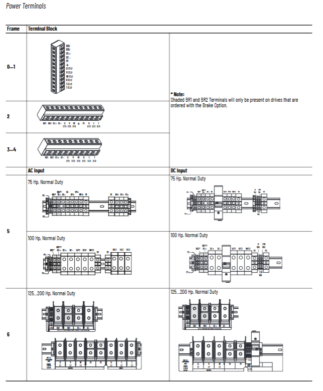
Complete table of wire diameters and tightening torques for different Frame power terminals, I/O terminals, encoder terminals, and shielded SHLD grounding terminals; Distinguish between power terminals, auxiliary control power supplies I/O、 Encoder and fan terminals.
Frame5-6 fans can be externally connected to 120/240VAC; Transformer taps can match different grid voltages.
I/O wiring
Distinguish between two types of control boards: Standard control board and Vector control board (with encoder interface).
Standard I/O board
2-channel differential analog voltage input ± 10V; 2-channel analog current 4-20mA input;
Analog output: ± 10V voltage; 4-20mA current output;
Relay output 2 sets (fault, operation);
6-point digital input, available in 24VDC or 115VAC versions.
Vector Control Board Added
PTC motor thermistor input; Additional simulation channels; 20B-ENC-1 encoder interface card (5V/12V encoder, differential orthogonal, Z-phase zero mark); Hardware enable jumper.
Typical wiring examples: potentiometer setting, joystick bipolar, 4-20mA, 2-wire/3-wire start stop, PLC output, relay output, encoder wiring, with corresponding parameter settings.
Note: 2-wire control mode will disable the HIM panel start button.
Mechanical installation
Installation posture: It must be installed vertically; Do not use gaskets to isolate the installation surface; Ensure ventilation up and down; The minimum gap between the upper and lower parts is 101.6mm (4 inches), and the left and right parts are 50.8mm.
Three installation methods:
DIN rail;
Panel screw installation IP20/NEMA1;
Flange installation (radiator protruding from cabinet, IP54); Independent wall mounted IP54.
Complete outline drawings, opening drawings (flange version), and weight (body+packaging) for each Frame (0-6); Contains information on lifting holes.
Temperature Description: Removing the top ventilation label will change the enclosure rating from NEMA1 to Open.
List of all options
1. Human Machine HIM
20-HIM-A0/A3/A6 local; 20-HIM-C3S/C6S remote panel installation; Supporting various DPI communication cables.
2. DPI communication adapter
20‑COMM‑B/C/D/E/ER/H/K/M/P/Q/S; USB adapter 1203- USB.
3. Feedback and IO spare parts: Encoder card 20B-ENC-1, detachable terminals.
4. Braking: Built in braking resistor kit, corresponding models for different voltage frames.
5. External accessories: terminal resistor, reflection wave suppression module, isolation transformer, input-output reactor (3%/5% impedance, 240V/480V/600V complete selection table).