ABB REF620 (Relion 620 series) feeder protection and measurement device
Overall Introduction
Two major hardware configuration versions
Configuration A: Traditional CT/VT input (conventional current voltage transformer);
Configuration B: Supports input from combination sensors (such as Rogowski coils).
The factory comes with default example configurations for reference only. Engineering applications must be reconfigured using PCM600 software; Timer, trigger, and timing logic can be built using signal matrix and graphical application logic to adapt to different on-site requirements.
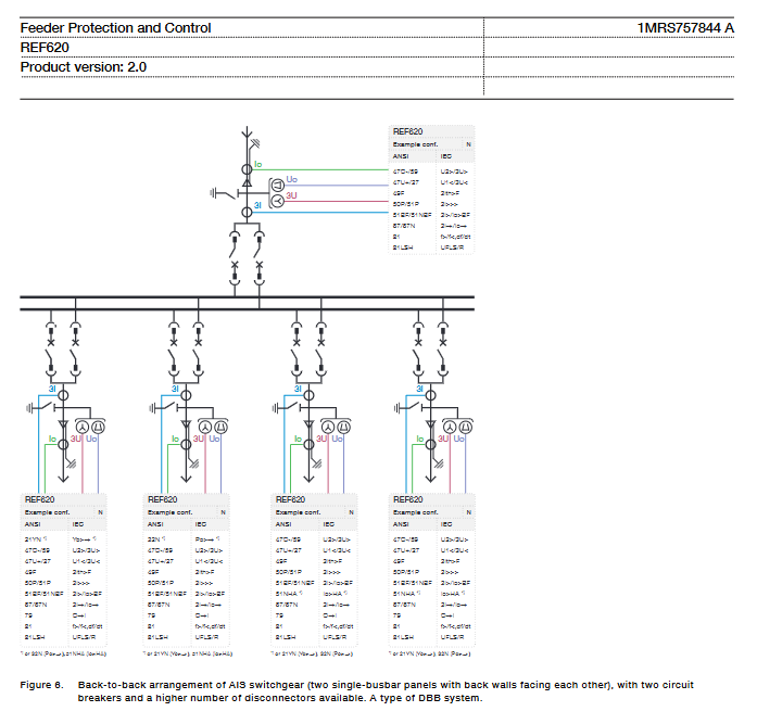
Application scenarios: Neutral point ungrounded, resistance grounded, impedance grounded distribution networks; Support multiple main connections including single bus, double bus, and multiple circuit breakers; Can implement protection logic for ring and mesh networks; When I/O is insufficient, an external RIO600 remote I/O module can be connected to expand the number of points.
Supporting system tool: PCM600 (IED management software), which completes parameter, logic, HMI screen, and communication configuration; Can be combined with COM600 gateway, MicroSCADA Pro, and System 800xA to form a complete substation automation system.
Complete protection function
Supports multiple protection curves from IEC and ANSI, with optional timed/inverse time limits; A large number of functions can be reused for multiple instances.
overcurrent protection
Three phase non directional overcurrent: low section, high section (2 groups), transient period;
Three phase overcurrent: low section x 2, high section x 2.
Ground fault protection (emphasis, distribution network application)
No directional grounding fault: low segment x 2, high segment x 1, instantaneous;
Directional grounding fault x 3; Admittance type grounding fault x 3; Power measurement (wattmeter) grounding fault x 3;
Transient/intermittent grounding faults, harmonic type grounding faults;
Unbalance protection: Negative sequence overcurrent, phase failure protection;
Voltage protection: residual overvoltage, three-phase overvoltage, three-phase undervoltage, positive sequence undervoltage, negative sequence overvoltage;
Frequency protection: up to 6 groups, can achieve over frequency, under frequency, df/dt frequency slip;
Thermal overload protection: three-phase thermal model protection for feeders, cables, and distribution transformers;
Other protections: under current (phase loss), circuit breaker failure protection x 2, excitation inrush current lockout; High impedance fault detection; Multi purpose universal analog protection (12 sets);
Optional arc light protection (ordering option): External optical lens sensor, paired with high-speed output, can achieve millisecond level tripping, used for arc fault protection in switchgear cabinets.
Control function
Circuit breaker control: 2 sets of examples;
Isolation switch control: 4 sets of examples; Grounding switch control: 2 sets; Simultaneously supporting manual device location collection and indication;
Synchrocheck: Determine voltage, phase angle, and frequency conditions to achieve safe grid connection and closing;
Multiple automatic reclosing DARREC;
Low frequency load shedding and recovery: up to 6 groups, load shedding based on frequency and df/dt;
All primary device control logic and lockout logic are configured in the PCM600 signal matrix.
Measurement, Electric Energy, and Electric Energy Quality
Three phase current, voltage, zero sequence current and voltage; Positive/negative/zero sequence components; Active, reactive, and apparent power; Active/reactive electricity; Frequency;
Power quality monitoring: current THD total harmonic distortion, voltage THD; Voltage fluctuations and three-phase imbalance; Can output short-term/long-term distortion statistics.
Wave recording, event and data recording
Disturbance Recorder: up to 12 analog channels+64 binary channels; Can be triggered by level/edge; The data is stored in COMTRADE format and saved in non-volatile memory;
Fault recorder: stores up to 128 fault records; DFT/RMS/peak to peak multiple sampling modes, with fault moment measurement values attached;
SOE event sequence record: up to 1024 timestamp events, no loss during power failure;
Load profile recording: An average cycle of 1-3 hours can be set to record long-term load changes.
Equipment self-monitoring and diagnosis
Trip circuit monitoring TCS: full condition monitoring of circuit breaker opening and closing circuits, identifying disconnection and loss of control power supply; Supports 2 sets of instances.
CT current circuit monitoring: detects abnormalities in the secondary circuit of the current transformer, triggers alarms, and locks relevant protections.
PT fuse failure monitoring: The negative sequence/Δ U-Δ I algorithm detects voltage circuit faults, alarms, and locks out voltage related protections.
Whole machine self-monitoring: continuously detects hardware and software failures and outputs alarms.
Access control: Level 4 role passwords (Browser/Operator/Engineer/Administrator), panels, WebHMI, PCM600 are all subject to permission control.
I/O hardware system
Divided into traditional transformer version (configuration A) and sensor version (configuration B)
Version analog input switch input BI switch output BO
Configuration A (CT/VT) 4 current+5 voltage 24 (expandable to 32) 14 (expandable to 18)
Configuration B (sensor): 3-channel combination sensor+1-channel residual current 16 (expandable to 24) 14 (expandable to 18)
Optional slot module (1 spare slot on the motherboard, choose one out of three)
BIO0005 ordinary I/O module:+8BI,+4BO, expand ordinary switch quantity;
RTD0003 thermistor/milliampere module: 6 RTD thermistor inputs, 2 0-20mA analog inputs; Used for collecting on-site simulated signals such as temperature and pressure;
BIO0007 high-speed output module:+8BI, 3-channel high-speed output HSO, with an action time of about 1ms, specially designed for time critical scenarios such as arc protection.
When I/O is insufficient, it can be extended remotely through RIO600 via IEC61850 GOOSE to achieve fast signal interaction.
Relay output specifications
Normal signal output and power output; High speed output HSO action time 1ms; supports TCS trip circuit monitoring function;
Binary input threshold can be software configured: DC18-176V.
Communication interface and protocol
Supported Protocols
IEC 61850 (GOOSE message, supports binary and analog GOOSE horizontal interlocking, meets the tripping performance of distribution network);
Modbus RTU / TCP; IEC 60870‑5‑103; DNP3 (serial port+TCP).
Ethernet redundancy solution: Supports PRP parallel redundancy protocol, HSR high reliability seamless ring network protocol, RSTP self-healing ring network, achieving zero switching time network redundancy.
Physical interfaces: RJ45 electrical port, LC multimode fiber, ST fiber; Debug the network port on the front panel.
Timing methods: SNTP network timing, IRIG-B hardware timing; The timestamp resolution is 1ms.
WebHMI web interface: default off, PCM600 on; Can browse data, events, and record waves, supports read-only mode, and can be accessed through a browser without software.
Local Human Machine HMI
Backlit LCD, capable of displaying editable single line diagrams (SLDs), showing the location of a device and real-time measurement values; Single line diagram can be drawn and downloaded on PCM600;
11 dual color programmable LED indicator lights; 16 panel programmable function buttons, each button comes with a status LED;
Local remote (L/R) key/button switch: Local mode only panel operation; Remote mode receives backend commands; Support external hard contact forced local setting to prevent remote opening and closing during maintenance.
Mechanical, environmental, and electrical technical parameters
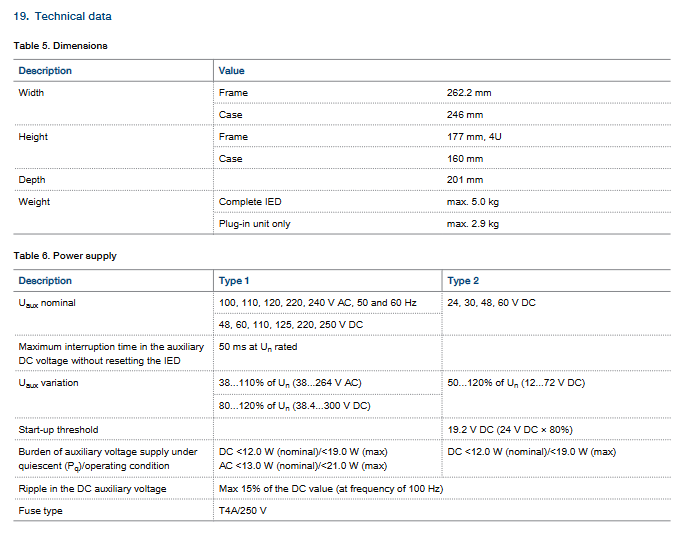
Installation methods: embedded (panel installation), semi embedded, wall mounted, 19 inch rack installation; 4U height; The maximum weight of the whole machine is 5kg, and the plug-in unit is 2.9kg;
Power supply: Supports AC 100-240V/DC 48-250V; DC24-60V is also optional;
Working temperature -25 ℃~+55 ℃; Short term -40~+85 ℃; Storage -40~+85 ℃; Maximum humidity of 93% without condensation; The highest altitude is 2000m;
EMC electromagnetic compatibility: meets the full set of IEC61000 series immunity tests; Meet the IEC60255 series relay protection equipment standards; CE certification, RoHS compliance;
Plug in mechanism: CT secondary automatic short circuit when the unit is pulled out; Mechanical coding to prevent incorrect insertion of different types of plugins.
Ordering code and options
Order code length string, key selection dimension:
Series: 620; Application: feeder F;
Analog type: A (CT/VT), C (sensor);
Optional modules: None/BIO0005/RTD0003/BIO0007 high-speed output;
Communication board: electrical port, fiber LC/ST, with or without HSR/PRP redundancy;
Protocol combinations: multiple combinations of IEC61850, Modbus, 103, DNP3;
Language: English/English+Chinese;
Option: Arc light protection; Power type; Product version 2.0.
Supporting software
PCM600: Core engineering software that completes all parameter, logic, signal matrix, GOOSE, HMI single line diagram configurations; Downloadable recording of waves and events;
Connectivity Package: IED data model, single line image library, used for interfacing with COM600 and SCADA systems;
Web HMI: browser access, only for monitoring and simple operations, unable to edit logic and signal matrices;
KEMA test report verification: The 620 series GOOSE trip meets the P1 level and message transmission is less than 10ms.