ABB DCS880 series DC speed control device
Basic Information
The DCS880 complete set of materials includes a quick guide, safety instructions, technical samples, hardware manual, firmware manual, service manual, hard parallel manual, 12 pulse manual, functional safety supplement, various option module manuals (fieldbus, IO expansion, encoder interface, etc.), PC tool Drive Composer materials, etc.
Device specifications: DCS880-S0x series, specifications H1~H8; Current range: H1-H5: 20-1190A; H6:900‑2000A; H7:1900‑3000A; H8:2050‑5200A, Used for armature speed regulation of DC motors.
Product code and options
Model code: including product series, bridge type (1 single bridge, 2 quadrants, 2 anti parallel double bridges, 4 quadrants), rated DC current, rated AC voltage, power connection position, excitation configuration, fan voltage, etc.
Plus Additional Code:
Operation panel: No panel 0J404; Bluetooth panel+J429; DPI H01 multi device daisy chain+J428.
Fieldbus: PROFIBUS (+K454)、DeviceNet (+K451)、CANopen (+K457)、Modbus (+K458)、EtherCAT (+K469)、 Ethernet IP/Profinet (FENA-11/21+K473/+K475).
IO Expansion: Simulate IO FIO-11, FAIO-01; Digital IO FIO-01, FDIO-01; Encoder interfaces FEN-01 (TTL), FEN-31 (HTL); DDCS communication module FDCO-01/02.
Functional safety, application programming authorization+S551, onboard excitation cancellation 0S163, etc.
Hardware boards: main control board SDCS-CON-H01, DCSLink board SDCS-DSL-H1x, power interface board SDCS-PIN-H01/H51, power board SDCS-POW-H01, optical power link SDCS-OPL-H01 (H7/H8), excitation interface SDCS-BAB-F01/F02 (H1-H4).
Safety instructions
1. Personnel qualifications
Only certified electricians are allowed to install and maintain; After the main circuit is powered off, a multimeter must be used to confirm that the input and DC bus ground voltage are close to 0V before operation can be carried out; It is prohibited to conduct voltage/insulation shake table tests on the device body, and only separate insulation tests can be conducted by disconnecting the motor and cable.
2. Grounding requirements
Drivers and motors must be reliably grounded with PE protection; Each device in the multi drive system is independently connected to a PE.
360 ° high-frequency grounding is installed at the entrance of the shielded cable cabinet; The leakage current of the driver is greater than 3.5mA DC, and a fixed PE connection is required; Residual current protectors must use B-type RCD.
Models with EMC filters cannot be used in IT ungrounded systems or high impedance grounded>30 Ω power grids.
3. Circuit board and fiber optic protection
The circuit board is a static sensitive device, and an anti-static wristband should be worn during operation; Pinch only the connector of the fiber optic cable and do not touch the end face of the fiber optic cable. The minimum bending radius is 35mm.
4. Mechanical safety (H4-H8 large models)
The whole machine is very heavy, only lifting ears are allowed to be used for lifting, and lifting the front cover is prohibited; If the center of gravity is high and tilted about 6 degrees, it will tip over; H4-H6 can only be placed with the back facing downwards; Install measures to prevent drilling dust from entering the interior of the equipment; Ensure cooling and ventilation.
5. Safe operation during operation
It is prohibited to use main power disconnection as a means of motor shutdown, and panels should be used instead IO、 Communication command start stop.
The emergency stop button must be configured with hardware; The STOP button on the panel does not equal emergency stop; When the control position is remote, the panel stop button is invalid.
The main circuit isolation switch must comply with EN60947-3 Class B and be locked in the open position during maintenance.
Mechanical installation
1. Installation environment
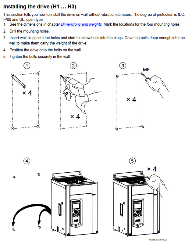
Vertical installation of the device; The wall must be vertical, non combustible, and have sufficient load-bearing capacity; Reserve maintenance and heat dissipation space up, down, front, and back; The maximum temperature of the incoming air is+40 ℃.
2. Open box inspection
H1-H3, H4, H5, H6, H7-H8 have corresponding packaging structures; H5 needs to disassemble and assemble the fan; H7/H8 removal of transportation fixed brackets; Open the box and inspect the appearance for damage, check the nameplate for information such as model, AC/DC voltage, current, fan parameters, SCCR short-circuit withstand, serial number, etc.
3. Installation method
H1-H5: Wall mounted installation, fixed with M6 bolts; After H5 installation is completed, the fan components need to be restored.
H6-H8: Only installed inside the cabinet, not wall mounted;
H7/H8 air intake comes from the bottom, left and right, and back; It is necessary to avoid the backflow of hot air inside the cabinet and install air guide partitions;
Multiple units are installed in parallel in the cabinet, with a minimum unit gap of 5mm when there is no cover plate;
The power connection can be connected using a copper bar adapter, with a maximum screw thread depth of 35mm; the cable must be tied to prevent damage from fan airflow.
Attachment: H1-H4 can use VBG4 standard terminal protection cover; H4 can use Lug bars for easy connection of DC cables.
Cooling duct parameters: The manual provides the area of the inlet and outlet for each specification, with a focus on preventing hot air recirculation.
Electrical installation planning
1. Selection of peripheral components for the main circuit
(1) Incoming reactor L1
The minimum relative impedance uk is ≥ 1%, and the upper limit does not exceed 10%; The common coupling point PCC has a power quality requirement of selecting a UK=4% reactor.
The use of dedicated isolation transformers can meet some impedance conditions; When the autotransformer is supplying power, it must still be equipped with a line reactor.
H1-H5 allows PCC voltage ≤ 600VAC; The manual provides the ND series reactor models corresponding to each power specification.
(2) Semiconductor fast fuse F1 (thyristor protection)
H1-H4: Semiconductor fast melting must be configured externally and cannot be replaced by ordinary fuses to avoid thyristor explosion and fire in case of failure.
H5-H8: The device has already integrated branch fast melting inside, and does not require external AC fast melting.
4-Q four quadrant feedback working condition, it is recommended to configure DC fast melting or high-speed DC circuit breakers on the DC side; The higher the proportion of feedback, the stronger the recommendation for DC fast melting.
Excitation circuit: DC side prohibited fuse; Use semiconductor fast melting F3.1 for semiconductor protection on the communication side; F3.2/F3.3 ordinary HRC fuses are used as line protection.
(3) Excitation system scheme
Multiple excitation configurations:
H1-H4: Onboard excitation;
H5/H6: Built in FEX-425Int excitation unit;
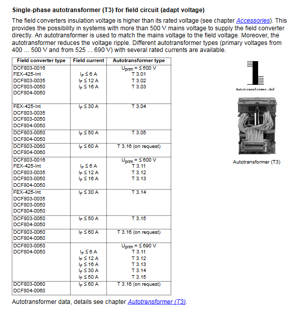
External excitation units DCF803-0016/0035/0050/0060, DCF804-0050/0060;
H1-H3 can act as a high-power exciter on its own.
DCF803-0016, FEX-425-Int, and DCF803-0035 require external excitation line reactors; High power DCF803/804-0050/0060 with built-in reactor.
The single-phase autotransformer T3 is used for excitation side voltage matching.
(4) Auxiliary Transformer T2
Provide power to the device control board and single-phase fan, input 380-690V, output 115/230V, power 1400VA.
(5) EMC filter E1
Only used for grounding TN/TT power grids; IT systems prohibit the use of EMC filters.
For devices larger than 100A, EN61800-3 does not mandate filters in industrial environments; Filter configuration is required for low voltage (400V) operation on the public network; The manual provides a selection table for NF3 filters of various specifications.
2. Start stop and emergency stop logic
The device is equipped with: On/Off, Start/Stop; Off2 (fast current interruption, used to feedback the working condition by first eliminating the regenerative current and then dividing the main contactor), Off3 (emergency stop, can be set to 0/1 type stop).
Off3 emergency stop mode can be set for slope deceleration or free parking; Coordinate the timing of time relays K15 and K16; The feedback system strictly prohibits breaking the main contactor when regenerative current is present.
Command source: Local IO, PLC communication, panel/PC tools, can be mixed for use; Parameter groups 06, 20, and 21 manage control words and emergency stop modes.
The US version scheme can be configured with DC contactors for energy consuming braking resistors.
3. Cooling fan
Each size corresponds to a different model of fan (H1-H4 are 24V internal fans; H4-H6 single-phase 230V; H7/H8 three-phase 400V level), provide power consumption, current, air volume, lifespan, and wiring terminals; The H1-H4 fan terminals are located at the top of the device; H5-H8 terminal X2/U1V1W1; There are clear regulations on cable diameter and tightening torque.
4. Power section monitoring
H1-H6: PTC thermistor isolation temperature measurement for radiator; Alarm first and then report a fault when the temperature exceeds the limit.
H7-H8: PTC temperature measurement at the air inlet, and pressure difference switch monitoring of cooling air volume; The differential pressure switch signal is connected to the fan confirmation DI.
5. Protection function
Short circuit: relying on fuses; The device itself protects the motor cable from short circuit (the cable is selected according to the rated current).
Thermal overload: The cable is selected according to the rated current, and the driver comes with thermal model protection; Multiple motor drives require independent protection for each motor circuit.
Motor thermal protection: supports motor thermal model calculation and external PTC/Klixon/Pt100 temperature sensors; The sensor wiring has insulation safety requirements.
Ground fault: There is no motor side ground fault protection inside the drive; Equipped with B-type RCD leakage protector.
6. Cable selection and tightening torque
Power cables: According to DIN VDE standards, provide the cable cross-sectional area and bolt torque for each model of armature C1/D1, incoming U1/V1/W1, and PE; Specification of excitation circuit cables.
The cross-sectional area of PE conductor follows IEC61800-5-1: S ≤ 16mm ², PE=S; 16<S≤35,PE=16; S>35,PE≥S/2。
Control cable:
Analog quantity and encoder: Double shielded twisted pair, with each signal being an independent pair;
Digital signals greater than 3m must be shielded;
24VDC weak current and 115/230VAC strong current cannot be in the same cable;
Encoder cable gives the wire diameter corresponding to different transmission distances;
The maximum remote cable for the operation panel is 3m, using CAT5e Ethernet cable.
Wiring specifications: power cable, control cable trunking; Cross as much as possible at a 90 degree angle; Minimum spacing between different types of cables; The two ends of the shielding layer are grounded (common ground), and if the ground potential is different, one end is connected to a Y capacitor.
Chapter on Electrical Wiring
Before powering on, check that the motor and excitation cables are disconnected. Only perform a 1kV DC insulation test on the motor/cable, with insulation greater than 1M Ω. It is strictly prohibited to shake the insulation of the drive body. Key points of IT ungrounded system.
Hardware layout of control board:
SDCS-CON-H01 terminal: XAI analog input, XAO analog output, XDIO digital IO, XDI digital input, XENC encoder, XTAC analog speed measurement, XSTO safety torque shutdown, XD2D device interconnection, relay output RO1-RO3, X205 memory unit slot.
3 F-type expansion slots Slot1/2/3, capable of inserting IO and bus adapters; The FEA-03 expansion adapter supports cascading multiple modules and setting node addresses.
Encoder wiring:
Support differential and single ended (push-pull) encoders; Jumper J4D selects encoder power supply 5V (default)/24V; J4A-J4C switches between differential/single ended mode.
Feedback direction error will report 7301 fault; The rotation direction can be corrected by swapping A+/A – or exciting F1/F2.
DCSLink communication (500k baud, CAN hardware, used for exciters, 12 pulse multi drive)
Bus topology, both ends must be connected to 120 Ω terminal resistors; Maximum total length of 100m; each node has a unique node number; Recommend DeviceNet cable; Different baud rates correspond to the maximum cable distance; Provide an example of wiring between DCS880 exciter and dual DCS880.
Hardware drawings
The manual includes multiple sets of system diagrams:
Block diagram of H1-H4 onboard excitation system; H5 with FEX-425-Int; H6 with FEX-425-Int; H1-H8 is equipped with external DCF803/804 excitation; H1-H3 serves as the excitation unit.
Fan wiring diagram, encoder differential/single ended schematic diagram, DCSLink bus wiring, emergency stop timing diagram, cabinet air duct anti backflow schematic diagram, nameplate sample diagram, and overall installation hole diagram.