ABB PFEA111/112/122 Strip Tension Controller
Principle
Pressductor ® Magnetostriction measurement principle: Two sets of mutually perpendicular windings inside the sensor; A set of AC excitation generates a magnetic field, and there is no magnetic coupling between the windings when there is no external force; When the tension of the strip is applied to the sensor, the magnetic properties of the steel change, the magnetic field couples, and the second set of windings induces voltage, with the voltage corresponding to the force applied; The sensor itself has no bending/stretching deformation and is resistant to impact overload.
System composition: Tension controller host+tension sensor (PFCL/PFTL/PFRL series), optional accessories: PFXC141 junction box, PXUB201 insulation amplifier, SD83x power module.
Installation (Mechanical+Electrical)
2.1 Mechanical Installation
IP65 (NEMA4) wall mounted type: wall mounted, shell sealed, with sufficient space reserved for opening and maintenance, cable connectors must meet UL certification requirements.
IP20 rail type: DIN 35 rail installation; As a protective grounding, the metal guide rail should be connected to the cabinet PE protective grounding; Installation of multiple units in the same cabinet requires SYNC synchronous wiring.
MNS cabinet installation specifications: cabinet splicing, floor fixing, front, back, left, right, and top ventilation gap requirements.
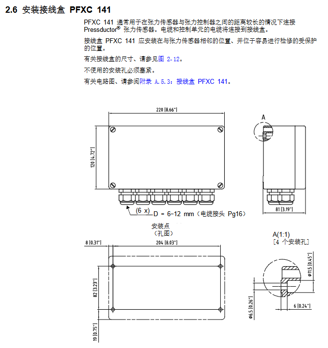
PFXC141 junction box: Used when the distance between the sensor and the controller is long, and installed close to the sensor side for protection.
2.2 Key rules for electrical wiring
Excitation cables and signal cables must be routed separately; Excitation 2 × 2.5mm ²; The signal is twisted pair shielded 2 × 2 × 0.5mm ²; The maximum length is 50m; the total cable resistance of the excitation circuit is ≤ 5 Ω.
Cable diagonal pairing: one pair for excitation and another pair for signal; The shielding layer is only grounded at one end, and the shielding lead out short wire is ≤ 50mm;
Stay away from power cables, with a minimum spacing of 0.3m, and cross at a 90 ° right angle;
IP20 shared cabinet: SYNC synchronization terminals must be interconnected to avoid mutual interference; The IP65 wall mounted version does not require synchronization.
Power Specifications
IP20 version: DC 18-36V;
IP65 version: AC 85-264V, 45-63Hz.
Optional peripherals
PXUB201 Insulated Amplifier: Achieve electrical isolation of analog signals, DIN rail installation, switchable voltage/current output, bandwidth.
SD83x series power supply: SD831/832/833, providing power to multiple PFEAs.
Appendix B-G includes mechanical installation, package angle gain calculation, dimensional drawings, and cable diagrams for six types of tension sensors: PFCL301E, PFTL301E, PFRL101, PFTL101, PFCL201, and PFTL201. Core concept Wrap Gain: The ratio of the actual tension T of the strip to the force FR measured by the sensor, depending on the angle of the guide roller wrap and the installation angle of the sensor; T=WrapGain × FR, range 0.5-20.
Debugging
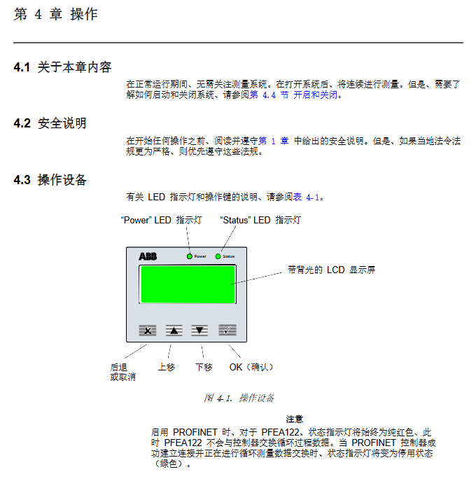
Operation panel buttons: Back Cancel, Up Move, Down Move, OK Confirm; Press and hold the OK button for 5 seconds to enter the configuration menu.
3.1 Preconditions for Debugging
Confirm that the wiring is correct; Master: sensor rated load, measurement mode (dual sensor standard roller/single sensor A-side/B-side), maximum process tension, analog output requirements, bus parameters.
3.2 Two Debugging Processes
There are two ways to quickly set up FastSetUp (easy debugging):
① Hang Weight: Hang a known weight weight on the idler roller, and the system automatically calculates the package angle gain; Suitable for hanging weights on site if conditions permit.
② Enter WrapGain: Calculate the WrapGain based on the mechanical drawing and fill it in directly. Quickly set up automatic filtering, 4-20mA, 0-10V output parameters.
Complete setup (fine configuration of all parameters)
Main menu settings
PresentationMenu displays menu language, engineering units (N/kN/kg/lbs/N-m, etc.), strip width, and decimal places; Supports linear tension units such as N/m and kN/m, and requires input of strip width
SetObject object object type standard roller (dual sensor), A-side single sensor, B-side single sensor; Single side mode internal automatic x 2 conversion of total tension
The rated load of NominalLoad must be consistent with the rated load on the sensor nameplate
ZeroSet zero adjustment is performed when there is no tension in the strip, compensating for the weight of the roller. The zero adjustment range is ± 2 × Fnom
SetWrapGain package angle gain weight calibration/manually input calculated value 0.5-20
VoltageOutput voltage output 0-10V range mapping, high and low limits, filter (15ms-1500ms multi-stage linear phase filter)
CurrentOutput current output 4-20mA mapping, high and low limits, filtering parameters
Miscellaneous menu bus parameters, factory reset settings
View the maximum load record and zero offset in the Serviceenu service menu; Reset peak value; Simulation function, which can simulate tension signals for debugging the backend PLC. When turned on, the status light turns red
Filter: Step response of 15~1500ms, corresponding to a cut-off frequency of 35Hz~0.25Hz, to suppress tension noise caused by roller shaking.
3.3 On site verification
Polarity check: Hand push the sensor, the reading must increase in the positive direction; Swap the positive and negative terminals of the signal when the reading is reversed;
Sensor function verification: Weight testing to determine if A/B sensors are working properly.
3.4 Fieldbus Communication
PFEA112:PROFIBUS‑DP(RS485)
As a DP slave station; Support addresses 0-125; The GSD file is in the appendix;
Loop upload two sets of tension (reuse voltage output filtering and current output filtering time respectively)+status fault bit; Only supports zero adjustment commands issued by PLC;
Support custom measurement range and load resolution LoadDivision; 16 bit complement code transmission.
PFEA122: PROFINET IO (Ethernet)
RT-Class1 real-time, with a minimum cycle time of 1ms; supports SNMP and LLDP; GSDML appendix provided;
Loop data: A+B total tension, A tension, B tension, status byte; PLC can issue zero adjustment instructions;
IP/MAC、 The subnet mask gateway is allocated by PLC; Can set bus filtering and load grouping; Support firmware upgrade via USB interface.
3.5 PXUB201 Insulation Amplifier Debugging
Dial switches S1 and S2 to switch between input and output modes (0-10V to 4-20mA, etc.) and bandwidth (10kHz/10Hz slow filtering).
Operation
Power on: external switch power supply; The Power light is constantly on; Status green light is normal; The red light represents an alarm/malfunction.
Operation menu loop display: total tension WebTension, A-side tension, B-side tension, A-B tension difference, alarm information.
Unit display logic: Automatically adjust the significant digits based on the rated load of the sensor; The decimal places can be set.
Alarm prompt: Fault warning appears, Status turns red; You can flip to the last menu to read the message, and the fault will be eliminated and the green light will automatically be restored.
In single-sided sensor mode, the other channel value is set to zero, and the total tension is 2 times the effective single channel measurement value.
Maintenance
preventive maintenance
Sensors: prevent corrosion; Tighten screws; Clean the gaps and debris to avoid additional force;
Controller: Check the tightness of terminals and the integrity of cables;
PFEA122 firmware upgrade for Windows computer via mini USB; It can be upgraded automatically using graphical tools, or manually by copying partition files; Measurement stopped during the upgrade period.
PFEA111/112 does not support USB firmware upgrade.
Fault Tracking
6.1 Classification of Fault Sources
Mechanical installation (zero drift, abnormal sensitivity), sensors (overload impact), wiring (shielding, excitation resistance, polarity), controller hardware.
6.2 Error (device malfunction, must be addressed)
Flash memory error, EEPROM error → controller needs to be replaced;
Power supply error → Check the voltage range of the power supply;
Sensor excitation error: Check the total resistance of the excitation circuit cable to be ≤ 5 Ω, and check for short circuit or open circuit.
6.3 Warning (affecting accuracy, not stopping)
PROFIBUS/PROFINET communication failure;
Multi machine synchronization warning;
Typical fault phenomena
High reading noise: shielding grounding error, power cable close distance;
Zero drift: Shielded grounding at both ends, excitation signal line not separated, multiple IP20 not synchronized with SYNC;
No signal after loading: signal polarity reversed, excitation circuit disconnected.
Downgrade operation function: Emergency response for single sensor failure
If one of the sensors is damaged, the faulty sensor can be disconnected and the corresponding excitation terminal can be short circuited; Change the SetObject menu to measure A/B on one side, and the equipment will continue production, but only tension can be collected on the single roll side.
Key points for replacing components
Replace controller: All parameters need to be reconfigured;
Replace tension sensor: Zero adjustment must be performed to reset the maximum load record.