LS Power Generation SV-IG5A Series Inverter Easy Operation Instructions
LS SV-IG5A series frequency converter simple operation manual, focusing on 0.4-22kW, single-phase 200V/three-phase 200V/three-phase 400V models, clarifying safety specifications, installation wiring, keyboard operation, parameter settings, fault protection, maintenance, technical specifications, and the entire process. The core control method is V/F and sensorless vector control, supporting keyboard/terminal/RS485 communication speed regulation, with complete protection for overcurrent, overvoltage, overload, overheating, etc., meeting EAC, CE, EN standards, suitable for industrial motor speed regulation scenarios.
Safety operation standards
Core Warning (must be followed)
After power failure, wait for ≥ 10 minutes and confirm that the DC bus voltage * *<DC30V * * before opening the cover operation
It is strictly prohibited to dismantle the panel while it is live, and it is strictly prohibited to connect power factor capacitors/surge suppressors/filters on the output side
Flame retardant installation is required, keep away from flammable materials, and prevent fires
Wiring and maintenance should only be carried out by professional electrical personnel
Grounding requirements
Voltage level, grounding impedance requirements, grounding method
200V level < 100 Ω third type grounding
400V level < 10 Ω special third type grounding
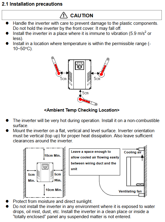
Installation and environmental requirements
Installation requirements
Environmental temperature: -10 ℃~+50 ℃ (non freezing)
Storage temperature: -20 ℃~+65 ℃
Humidity: ≤ 90% RH (no condensation)
Altitude: ≤ 1000m, vibration * * ≤ 5.9m/s ² (0.6G)**
Protection level: IP20
Installation spacing
Up and down: ≥ 10cm
Left and right: ≥ 5cm
Vertical installation (top and bottom out) to ensure smooth ventilation of the heat dissipation duct
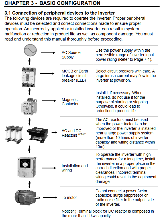
Electrical wiring specifications
Main circuit terminal
Power input: R/S/T (three-phase), single-phase connected to R/T
Motor output: U/V/W (strictly prohibited from being connected in reverse with the power supply)
Braking resistor: B1/B2 (no short circuiting allowed)
Grounding: Dedicated grounding terminal, strictly prohibited from being shared with the screws of the chassis
control terminal
Multi functional inputs: P1~P8 (forward rotation, reverse rotation, emergency stop, reset, jog, etc.)
Analog quantities: V1 (0~10V), I (0~20mA), VR (10V/100mA)
Communication: S+/S – (RS485)
Output: MO (open collector electrode), 3A/3B/3C (relay)
Wiring specifications
Cable: * * 600V, 75 ℃ * * copper core wire, strictly tightened according to torque
Motor line length: ≤ 50m (15kHz), ≤ 100m (5kHz), ≤ 200m (2.5kHz)
Separate wiring for control and power lines, with a spacing of * * ≥ 15cm**
Keyboard and Basic Operations
Keyboard composition
Display: 7-segment LED, FWD/REV/RUN/SET indicator lights
Buttons: RUN, STOP/RESET, ↑/↓/←/→ ENT
parameter group
DRIVE group: target frequency, acceleration and deceleration time, operating mode
FUN1 group: V/F curve, torque boost, DC braking
FUN2 group: PID, carrier frequency, control mode, parameter initialization
I/O group: terminal definition, communication parameters, multi-stage speed
Common Operations
Frequency setting: 0.00 → ENT → Digital setting
Parameter initialization: H93=1 Reset to factory settings
Fault check: Drive group pages to nOn to view fault codes
Core functions and parameters
control mode
0: V/F control (default)
1: Slip compensation
3: Sensorless vector control (up to 300Hz)
key parameters
Maximum frequency: 400Hz (vector mode 300Hz)
Carrier frequency: 1-15kHz (the higher the noise, the smaller the leakage current)
Acceleration and deceleration time: 0~6000s
Overload capacity: 150%/1 minute
Operation mode
Keyboard operation, terminal control, RS485 communication, remote keyboard
Frequency given: keyboard V1(0~10V)、I(0~20mA)、 Multi speed PID
Fault protection and maintenance
protection function
Overcurrent, Overcurrent 2, Grounding Fault, Inverter Overload
Overvoltage, undervoltage, output phase loss, cooling fan failure
Hardware malfunction, communication malfunction, external malfunction
maintenance cycle
Remarks on component replacement cycle
Cooling fan 3-year forced air cooling model
4-year preventive failure of main circuit capacitor
Control board capacitor 4-year preventive failure
Technical specifications
Power coverage
Single phase 200V: 0.4/0.75/1.5kW
Three phase 200V: 0.4~22kW
Three phase 400V: 0.4~22kW
output frequency
0.1~400Hz, Resolution 0.01Hz
certification standard
EAC、CE、EN61800‑3、EN50178、EN61000‑4‑2/3/4/5/6
Key questions and answers
Question 1: What is the most common fatal mistake in the main circuit wiring of iG5A frequency converter? What consequences will it cause?
Answer: The most common mistake is to connect the power supply R/S/T to the motor terminals U/V/W. Consequence: Directly damaging the internal power module of the frequency converter, which cannot be repaired and is not covered by the warranty. Correct connection: Power → R/S/T, Motor → U/V/W.
Question 2: How to quickly restore the iG5A frequency converter to its factory default parameters? What is the operation path?
answer:
Enter FUN2 group (parameter starting with H)
Find H93 (parameter initialization)
Set to 1 (all initialized)
Press ENT to save, it will take effect after restarting
Applicable scenarios: parameter confusion, debugging exceptions, and changing application scenarios.
Question 3: What are the most common causes and solutions for overvoltage (OV) faults in frequency converters?
Answer: Common reasons:
The deceleration time is too short, and the feedback energy from the motor cannot be released
The power supply voltage is too high
The load inertia is large, and there is no brake resistor installed
Solution:
Extend deceleration time
Install braking resistor (B1/B2)
Check if the input voltage is within the rated range of * * ± 15% * *