TOSHIBA TOSBERT VF-S15 Inverter Description
TOSHIBA VF-S15 series three-phase/single-phase frequency converter detailed user manual, covering single-phase 240V/three-phase 240V/three-phase 500V, 0.2~15kW models. Based on safety regulations, the system explains installation wiring, panel operation, parameter setting, V/F and vector control PID、 The entire process includes multi-stage speed, braking, protection, communication, and maintenance. The core control includes V/F, sensorless vector, and energy-saving control. It has full protection against overcurrent/overvoltage/overload/overheating, supports RS485 and CANopen communication, and is suitable for general industrial speed control scenarios such as fans, water pumps, conveyor belts, and cranes. It emphasizes strong safety rules such as 15 minutes of power outage and voltage<45V before operation.
Safety regulations (mandatory requirement)
core warning
After power failure, wait for ≥ 15 minutes to confirm that the charging light is off and the DC bus voltage is less than 45V before operation.
It is strictly prohibited to open the cover with electricity, connect capacitors/absorbers on the output side, or modify or disassemble the machine.
It must be reliably grounded, flame-retardant installed, and equipped with emergency stop devices.
Applicable restrictions
Only used for three-phase induction motors, single-phase input models cannot drive single-phase motors.
Prohibited for use in high-risk scenarios such as medical, aviation, nuclear control, and manned equipment.
Product specifications
Project specifications
Power range single-phase 240V: 0.2~2.2kW; Three phase 240V/500V: 0.4~15kW
Input voltage single-phase/three-phase 200~240V; three-phase 380~500V
Output frequency 0.1~500Hz, resolution 0.01Hz
Control mode V/F, vector, automatic torque, energy-saving, dynamic energy-saving, PM motor
Overload capacity 150%/1min (constant torque); 120%/1min (variable torque)
Protect against overcurrent, overvoltage, undervoltage, overload, overheating, grounding, and phase loss
Installation and Environment
Environmental Requirements
Temperature: -10~60 ℃, humidity ≤ 90% RH, altitude ≤ 1000m.
Installation: Vertical installation, with a distance of ≥ 10cm from top to bottom and ≥ 3cm from left to right, away from vibration and dust.
Wiring specifications
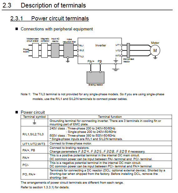
Main circuit: Power supply → R/L1, S/L2, T/L3; Motor → U/T1, V/T2, W/T3.
Control circuit: Analog VIA (0~10V), VIB, VIC (4~20mA); Digital quantities S1~S3, F, R, RES.
Grounding: 240V level < 100 Ω, 500V level < 10 Ω, use thick short dedicated line.
Panel and Operation Mode
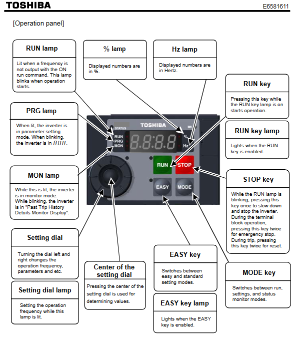
panel button
RUN/STOP: Run/Stop; MODE: Switching modes; EASY: Simple/Standard Parameter Switching.
Knob: Adjust frequency/parameters; Press the knob: Confirm.
three major modes
Standard monitoring: Display frequency, current, and voltage.
Parameter settings: Simple mode (commonly used 10 items), Standard mode (full parameters).
Status monitoring: Real time monitoring of operation, faults, and terminal status.
Quick Operation
Run command: panel/terminal/communication (cmod setting).
Frequency command: knob/analog/communication/multi speed (fmod setting).
Core parameters and functions
Basic operating parameters
Acceleration and deceleration time (acc/dec): 0~3600s.
Maximum frequency (fh): 30-500Hz; Upper and lower limit frequencies (ul/ll).
Base frequency (vl) and base voltage (vlv): determine the V/F curve.
Motor Protection
Electronic thermal relay (thr): set according to the rated current of the motor (10-100%).
Protection features: Standard motor/VF dedicated motor is optional.
Advanced control functions
15 segment speed: Terminal switching with multiple frequency segments (sr0~sr15).
PID control: closed-loop constant voltage/constant current/constant speed.
Jump frequency: 3 groups, avoiding mechanical resonance.
Sleep function: Automatic shutdown after continuous operation at the lower frequency limit.
Jogging: frequency 0~20Hz, can be set for deceleration/free parking/DC braking.
braking function
DC braking: The starting frequency, current, and time can be adjusted.
Dynamic braking: External braking resistors (PA/+, PB) are used to suppress overvoltage tripping.
Overvoltage limit: automatically extends deceleration to prevent regenerative overvoltage.
Communication and I/O
communication
RS485: Modbus protocol; CANopen is optional.
Remote panel: local/remote undisturbed switching.
I/O terminal
Digital input: forward to F, reverse to R, reset RES, multi speed, fault reset.
Analog input: 0~10V, -10~10V, 4~20mA.
Output: FM analog meter, relay (fault/operation), open collector electrode.
Fault handling and maintenance
Common Faults
OC: Overcurrent → Acceleration too fast, motor short circuit, wiring error.
OV: Overvoltage → Rapid deceleration, no brake resistor connected, high power supply.
OL: Overload → Motor is too small, load is too heavy, and thermal relay setting is improper.
OH: Overheating → blocked air duct, high ambient temperature, fan failure.
maintenance cycle
Cooling fan: Replace every 3 years.
Main capacitor/control board capacitor: replaced every 4 years.
Restore to factory settings
Parameter typ=3: manual initialization; Typ=13: Fully initialized.
Key questions and answers
Question 1: What is the most fatal wiring error of VF-S15? What consequences will it cause?
Answer: The most fatal mistake is to connect the power input to the motor output terminal U/T1-V/T2-W/T3. Consequence: Instantly breakdown the power module of the frequency converter, resulting in direct scrapping and not covered by warranty. Correct connection: Power supply → R/L1, S/L2, T/L3, motor → U/T1, V/T2, W/T3.
Question 2: How to quickly set 15 speed segments and switch through terminals? What are the core parameters?
answer:
Set the source of the running instruction: cmod=0 (terminal control).
Set the frequency of each segment: sr0~sr7, f287~f294 (0~15 segment speed).
Terminal allocation:
S1=SS1、S2=SS2、S3=SS3、RES=SS4。
Logic: Combining 4 terminals for binary switching with 15 speed segments, with the highest priority.
Core parameters: cmod, sr0~sr15, f114~f116 (terminal function).
Question 3: What are the three most effective solutions for frequent OV overvoltage tripping?
answer:
Extend deceleration time (dec) and reduce feedback energy rate.
Connect external braking resistors (PA/+, PB) and activate f304=1 (braking function).
Activate the overvoltage limit function (f305=2) to automatically suppress DC bus overvoltage.