Allen Bradley 160-IB1 InterBus Communication Module
The official user manual for the Allen Bradley 160-IB1 InterBus communication module (firmware 1.00) is dedicated to the 160 SSC C-series frequency converter. It is connected to the InterBus bus through a 9-pin D-shell interface and uses the DRIVECOM 20 protocol. It supports reading and writing of 3-digit process data and PCP parameters, and can be controlled by PLC through I/O messages for frequency converter start stop, speed regulation, and status monitoring. It has three working modes: power on/run/fault, and 5 LED status indicators. It requires configuring P46/P59/P66 core parameters and is compatible with EMC/low voltage commands. It provides a complete installation, wiring, configuration, programming, and fault troubleshooting guide.
Product Fundamentals
160-IB1 is an InterBus slave communication module launched by Rockwell Allen Bradley, which is only compatible with 160 SSC C series and above frequency converters, achieving high-speed digital communication between frequency converters and InterBus master stations (PLCs).
Firmware version: 1.00
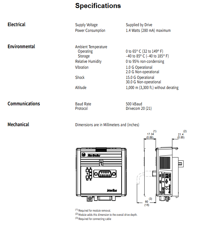
Communication interface: 9-pin D-shell (IN/NEXT cascade)
Power supply: provided by frequency converter, maximum 1.4W/280mA
Certification: Compliant with Low Voltage 73/23/EEC, EMC 89/336/EEC
Protocol: DRIVECOM 20 (Part 21) InterBus PCP
Hardware and Interface
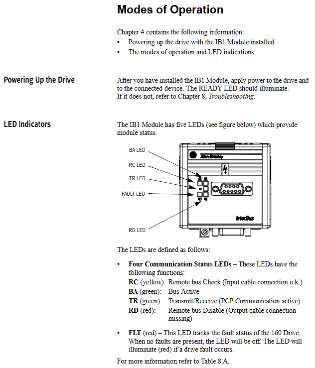
1. LED indicator lights (5 pieces)
Meaning of LED color
RC yellow remote bus verification (input normal)
BA green bus activation
TR green PCP active transmission and reception
RD red output bus not connected/disabled
FLT red frequency converter fault
2. Installation and wiring
Installation: Replace the inverter keyboard/display panel and secure it with a snap fastener
Grounding: IB1 grounding terminal short circuited to frequency converter TB3-3, wire diameter ≥ 1.5mm ²
Communication: Bus cascading connection, with a vacant NEXT port at the end to achieve terminal matching
Stop circuit: TB3-7 and TB3-8 must be short circuited, otherwise they cannot be started
Working mode
power-on mode
Module self-test, successfully entered operation mode (RC constantly on, TR flashing); Failed to enter fault mode.
operation mode
BA is constantly on as a slave station responding to master station instructions, processing process data and PCP.
failure mode
FLT lights up, communication is abnormal or the frequency converter is faulty, it needs to be checked and reset.
Data Protocol (Core)
The module adopts dual channel communication:
Process data channel (high-speed cycle)
Master Station → Slave Station (3 words): Control word, speed setting, diagnosis
From slave station to master station (3 words): status word, speed feedback, diagnosis
PCP parameter channel (low-speed non periodic)
Read and write frequency converter parameters, attributes, fault codes, index example:
0x5FF0: Read display parameters
0x5FF1: Read program parameters
0x5FF9: Write program parameters
0x603F: Read fault code
Key parameter configuration (must be set)
Function of parameter setting values
P46 [Input Mode] 2 or 6 Enable network control
P59 [Frequency Select] 1 Frequency Source=Network
P66 [RPM Scaling] motor rated speed calibration
P56 [Reset Functions] 2 parameter modification takes effect after restarting
Control and Status Words (DRIVECOM 20)
1. Control word (low byte)
06h: Ready
0Fh: Running
0Eeh: Quick Stop
2. Status word (low byte)
01h: Ready
03h: Powered on
07h: Running
08h: Fault
Network Configuration and Programming
Main station: SLC500+SST IBS SLC scanner
Software: IBS CMD G4 configuration network
mapping
Output: O: 3.0=control word, O: 3.1=speed given
Input: I: 3.0=status word, I: 3.1=speed feedback
Logic: Write control words and speed through MOV instructions to achieve start stop and speed regulation.
Fault diagnosis
1. Communication fault code
Code fault handling
7500 protocol fatal error restarts main station/frequency converter
7510 serial port unresponsive check module interface and firmware
7520 bus loss check cable, cascading
2. Common faults of frequency converters
03/04: Undervoltage
05: Overvoltage
08: Overheating
12/13: Overcurrent
38~43: Grounding/phase to phase short circuit
Key issues
Question 1: What 3 parameters must be configured for the IB1 module to enable the frequency converter to accept network control? How does it take effect after configuration?
Answer: Must be configured with:
P46=2 or 6 (enable network command)
P59=1 (frequency from network)
P66=Rated speed of motor (speed calibration)
Effective method: Set P56=2 or power on and off again.
Question 2: What is the difference between the process data channel of IB1 and the PCP parameter channel? What scenarios are they used for?
answer:
Process data channel: periodic high-speed transmission (3-word input+3-word output), used for real-time control such as start stop, speed setting, and status feedback.
PCP parameter channel: non periodic low-speed, used for configuration operations such as reading and writing parameters, reading faults, and changing limits, not suitable for real-time control.
Question 3: Why do TB3-7 and TB3-8 have to be short circuited when the inverter is networked through 160-IB1? What faults may occur if it is not short?
answer:
TB3-7/8 is the hardware stop enable circuit, and a short circuit represents “allow start”.
Failure to short circuit will trigger fault 22 (Stop Input Missing), causing the frequency converter to malfunction and rendering the network startup command invalid.