Pilz PSWZ X1P Safety Static Monitoring Relay
Product Overview and Usage
PSWZ X1P is a safety static monitoring relay developed by Pilz, which is used to monitor whether the motor is completely stationary after the equipment is stopped, and only allows the safety door to open or the dangerous action to be released in a stationary state.
Applicable: EN 60204-1 Safety circuits, equipment with dangerous moving parts
Measurement method: Detect the regenerative residual voltage after the motor is powered off. If the voltage is below the threshold, it is judged to be stationary
Safety specifications (core)
Safety standard level
EN ISO 13849-1 PL e,Category 4
EN IEC 62061 / 61508 SIL 3
PFHd (hazard failure frequency) 6.23 × 10 ⁻⁹/h
Mission Time (TM) 20 years
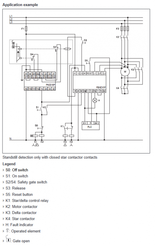
Hardware structure and terminals
Measurement input
L1/L2/L3: Connected to motor winding, supports up to 690V
Dual channel: CH1 (L1-L3), CH2 (L2-L3)
power input
A1 / A2:24~240V AC/DC, Wide voltage compatibility
control input
Reset input: High level>15V effective, low level<5V
Feedback loop Y1-Y2: Monitoring external contactor
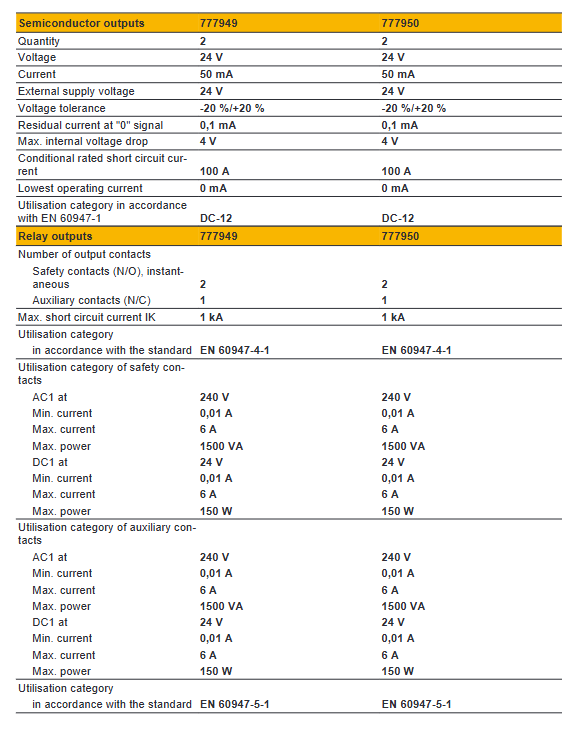
relay output
Safe output: 13-14, 23-24 (2-channel normally open, redundant)
Auxiliary output: 41-42 (1 normally closed, not suitable for safety circuits)
Semiconductor output
Y32: Status output (static=high)
Y35: Fault output (fault=high)
Working principle
Power on process
Perform a 1.5s self-test after powering on to test the output, measurement circuit, and feedback circuit
Self check passed and the circuit is normal, entering standby mode
Static judgment logic
Dual channel voltage lower than Uon at the same time → judged as stationary
The safety contact is closed, and the OUTPUT light is on
Start/motion judgment
Any channel voltage higher than Uoff=2 × Uon → judged operation
Redundant disconnection of safety contacts, output prohibited
Fault status
Exceeding simultaneity time (maximum 7s) → FAULT light on
Reset pulse is required to clear the fault
Electrical parameters (key)
Parameter values
Measurement voltage range: 0~690V
Response threshold Uon 7.5mV~3V (adjustable for multiple models)
Release threshold Uoff 2 × Uon
Power supply range 24~240V AC/DC
Simultaneous monitoring time up to 7 seconds
Safe contact capacity AC1: 6A/240V; AC15: 3A/230V
Insulation withstand voltage 6kV, 690V level
Working temperature -10 ℃~+55 ℃
Protection level: body IP40, terminal IP20
Installation and wiring requirements
Install
35mm DIN rail installation, can be installed in any direction
Installation cabinet protection ≥ IP54
Wiring specifications
The measurement line uses shielded cables, and the shielding layer is grounded at one end
Separate wiring of control lines and power lines
The safety output front-end must be equipped with a fuse (maximum 6A fast melting)
threshold setting
Potentiometer adjustment, if the CH.1 IN/CH.2 IN light is on when the motor is stationary, it is considered qualified
Status and fault indication
Meaning of LED
POWER power supply is normal
CH.1 IN/CH.2 IN channel 1/2 reaches the static threshold
OUTPUT safety contact closed
Fault (asynchronous, open circuit, self-test failure)
Maintenance and testing
Weekly testing: Start the motor → Stop → Confirm that it is stationary before closing the output
Replacement must comply with electronic waste regulations
Prohibition of modification, disassembly, and unauthorized maintenance
Key issues
Question 1: What is the function of the “dual channel redundant monitoring” of PSWZ X1P? How to use a single-phase motor?
Answer: Dual channel monitoring is used to improve safety and reliability, and any channel failure can still be safely detected; When using a single-phase motor, the equipment will automatically allocate a single measurement signal to two channels, achieving equivalent redundant monitoring while still maintaining the PL e/Cat.4 safety level.
Question 2: What is the relationship between the static threshold Uon and the release value Uoff? Why is it designed like this?
Answer: Release value Uoff=2 × Uon, using hysteresis design. The purpose is to prevent frequent suction/disconnection of output contacts when the voltage fluctuates near the threshold, avoid contact vibration and system instability, and ensure clean and reliable safety status determination.
Question 3: What are the common reasons and reset methods for PSWZ X1P experiencing FAULT light on and safety contacts unable to close?
Answer: Common reasons: ① The dual channel voltage is not synchronized for more than 7 seconds; ② The measurement circuit is open/disconnected; ③ Feedback loop disconnected; ④ Self check failed. Reset method: Apply a high-level → low-level pulse signal to the reset input terminal to clear the fault.