MITSUBISHI ELECTRIC GOT1000 Series Connection Manual
Positioning and Applicable Scope
GOT1000 series graphical operation terminal connection manual, numbered sh080871engw, is used to guide communication between GOT and the following devices through GT Works3:
Microcomputer (microcontroller/embedded controller)
MODBUS RTU/MODBUS TCP devices
Sound output, external I/O, fingerprint authentication, barcode reader
VNC remote, video/RGB, printer, multimedia RFID
Covered models: GT16, GT15, GT14, GT12, GT11, GT10 full series.
Safety regulations (core mandatory requirements)
The document emphasizes safety through Warning/Caution grading:
Design Warning
GOT malfunction may result in output holding, and an external monitoring circuit must be configured.
Touching is still effective when the backlight is turned off, which can easily cause misoperation.
Multi touch can cause the analog resistive screen to malfunction.
The network needs to deploy firewalls/VPNs/antivirus to prevent network attacks.
Installation Warning
Disassembly and assembly must be completely powered off.
The installation option board needs to be anti-static.
The tightening torque of screws must comply with regulations.
Wiring warning
The separation between strong electricity and communication lines should be ≥ 100mm.
Must be Class D grounded.
Maintenance Warning
Do not touch the terminals when powered on.
Batteries are prohibited from being charged, disassembled, or heated.
Monitoring preparation process (standard steps)
Communication interface settings
Configure channels, manufacturers, device types, drivers, and interfaces in GT Designer 3.
Supports 4 channels, enabling simultaneous connection of multiple devices.
I/F communication settings
Allocate channels and drivers for standard interfaces (RS232/RS422/485/Ethernet/USB).
RS232 5V power supply can be enabled.
Write OS and project data
Write system OS, drivers, engineering, and communication configurations to GOT via USB/Ethernet.
Support verifying whether the write is successful.
Installation options and wiring
The bus unit must be installed in the first segment of the expansion interface.
Calculate the total power consumption within the GOT power supply capacity.
Verify connection
Use the utility to check if the communication driver is working properly.
Ping test/station monitoring confirms the link.
View error codes and communication status.
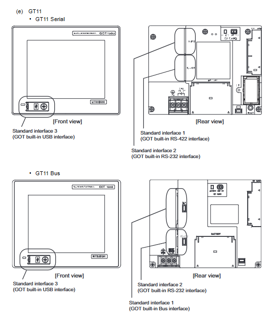
Hardware interface and cable specifications
1. Interface type
Interface applicable model connector
RS-232 full series D-Sub9-pin/terminal block
RS-422/485 full series D-Sub 9-pin/14 pin/terminal block
Ethernet GT16/GT15/GT14/GT12 RJ45
USB Full Series USB Slave/Master
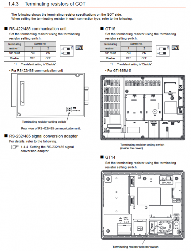
2. Terminal resistance setting
RS-422/485 needs to be set to 100 Ω/330 Ω or turned off.
The switch position is located on the body or interface unit depending on the model.
3. Power supply capacity (typical)
table
Maximum power supply of the model
GT16 high-end 2.4A
GT15 mid-range 1.74-2.2A
GT14/GT12/GT11 1.3A
Microcomputer connection (core communication function)
1. Working method
host ↔ GOT reads and writes internal virtual devices.
Support interrupt output and actively report events.
2. Virtual device area (key)
Equipment type, scope, and purpose
D letter 0~4095 system status/user area
User data from R to 4095
L/M bit 0~2047 bit status
SD character 0-15 clock/error code
SM bit 0-63 interrupt/clock flag
3. Communication formats (15 in total)
Format 1~2: GOT-A900 compatible
Format 3-6: A series 1C frame
Format 7-10: QnA compatible with 3C/4C frames
Format 11-13: DEC Memory Link
Format 14-15: GOT-F900 compatible
4. Core instructions
RD/WD: Batch Reading and Writing
RR/RW: Random Read Write
TR/TS: Read/Write Clock
MODBUS connection
MODBUS RTU
Interface: RS232/RS485
Settings: Station number, baud rate, verification
MODBUS TCP
Ethernet, IP configuration, port 502
Support multi slave station monitoring
Can connect third-party PLCs such as Schneider and Yokogawa.
Peripheral Connection List
The document fully covers the following peripheral connections:
Sound output unit
External I/O devices
Fingerprint authentication device
Bar code reader
PC remote operation
VNC Server
Video/RGB input/output
Printer (PictBridge/serial port)
multimedia
RFID
Each category provides: system diagram, wiring, GOT settings, and precautions.
Fault and status monitoring
Error code storage
SD2 stores communication error codes (parity/overflow/format error).
Station monitoring
The GS register records the fault station number and status.
Ethernet diagnosis
Ping testing, IP conflict checking, and connection testing.
key issue
Question 1: What are the functions and usage restrictions of virtual devices D13/D14 and SM0~49 of GOT in microcomputer connection?
answer:
D13/D14 is used for interrupt output, and after writing data, GOT actively sends data to the host.
Trigger interrupt code output when SM0-49 status changes (such as 50H, 51H).
Limitation: Interrupt triggered only by GOT side operation; Host write not triggered; The interrupt can be turned off by SM52=ON.
Question 2: What are the mandatory location rules for installing GOT1000 extension modules? What will happen if we exceed the rules?
answer:
The bus unit, MELSECNET/H, and CC Link unit must be installed in the first segment of the expansion interface.
The video/RGB/multimedia unit must be installed in the first paragraph.
The CF unit is installed in the last section.
Incorrect installation location can result in module recognition, malfunction, and communication abnormalities.
Question 3: How to choose 15 message formats supported by microcomputer connection in engineering? What is the most commonly used type?
answer:
Selection criteria: Controller protocol type.
New projects should prioritize formats 7-10 (QnA MC protocol), which are stable and universal.
Old system migration: Select the corresponding compatible format according to the original model.
Multi machine networking: Supports a 1: N structure with station numbers using formats 14-15.