GE AT868 AquaTrans ™ Single/dual channel ultrasonic water flow transmitter
Product basic information
GE AT868 AquaTrans ™ This is a single/dual channel ultrasonic water flow transmitter, measured using the correlation time difference method, with a protection level of NEMA 4X/IP66, dimensions of 6 × 4 × 3 in (152.4 × 101.6 × 76.2 mm), and a weight of 2.2 lb (1 kg).
Core specifications
Project parameters
Power supply 85-265 VAC (47-65 Hz)/12-28 VDC
Maximum power consumption of 10 W
Measurement range -40~40 ft/s (-12.2~12.2 m/s)
Range ratio 400:1
Accuracy>6 inches for pipelines: ± 0.5%~2%; ≤ 6 inch pipeline: ± 2%~5%
Repetitive insertion type ± 0.2% FS; clamping type ± 0.2%~0.5% FS
Environmental temperature -10~55 ℃ (working); -40~70 ℃ (storage)
Output 1 isolated 4-20 mA (maximum 600 Ω); 1-channel pulse/frequency output (0.1~10 kHz)
Communication standard RS232; Optional RS485
Installation requirements
Site selection requirements
Sensor upstream * * ≥ 10 times diameter straight pipe section, downstream ≥ 5 times diameter * * straight pipe section
Install the horizontal tube sensor on the side to avoid air accumulation at the top/slag accumulation at the bottom
The instrument box is installed nearby, and the sensor cable is up to 1000 ft (300 m) long
Wiring specifications
Power supply: The longest grounding pin is equipped with a visible power-off switch (EU LVD) within 1.8 meters
Sensor: The length difference of cables in the same channel is ≤ 4 inches (10 cm) (≤ 2 MHz); ≤0.5 in(1.25 cm)(>2 MHz)
Analog quantity: load < 600 Ω
Pulse output: External power supply is prohibited
CE compliance: All cables are shielded and grounded, with free holes sealed.
Programming configuration (core steps)
Channel activation: CHx ACTIV is set to TRANS to enable the channel
System unit: CHx SYSTM Set volume/cumulative/mass flow units and decimal places
Pipeline parameters (CHx PIPE)
Material: Steel/Cast Iron/Copper/Aluminum/Plastic/Other (Input Sound Speed)
Outer diameter, wall thickness, path length P, axial length L
Lining: Material, Sound Velocity, Thickness
Fluid: Water (0-100 ℃/0-260 ℃)/Oil/Other (Input Sound Velocity)
Signal threshold (CHx SETUP-SIGNL)
Signal low limit: 40
Related peak value: 100
Sound speed deviation: ± 20%
Speed range: -40~40 ft/s
Acceleration limit: 15 ft/s ²
Global Settings (GLOBL)
System units: Imperial/Metric
Error handling: Keep output/Stop accumulation
Communication: Address 1, baud rate 9600
Display: Loop displays up to 4 parameters
Display and operation
LCD adjustment: adjust backlight and contrast through potentiometer
Accumulated amount reset: panel button/external switch/PanaView software
Measurement control: Only PanaView supports pausing/restarting measurements
Calibration process
Analog calibration
Low point: 4 mA
High point: 20 mA
Linear testing: 0-100% segmented verification, error ≤ ± 0.005 mA
Frequency/pulse output
Frequency: 10-100000 Hz
Pulse: minimum conductivity of 50 μ s, set unit/pulse
Error codes and diagnosis
Common Error Codes (Table)
Root cause handling of code issues
E1 low signal cable/sensor/flow slot fault inspection wiring and coupling
E2 Sound Speed Error Parameter/Flow State Anomaly Check Sound Speed and Adjust Sensor
E3 speed exceeds the range, flow rate exceeds the set adjustment range threshold
E4 signal quality poor interference/poor alignment troubleshooting electromagnetic interference
E5 amplitude abnormal medium containing gas/coupling difference improvement sensor installation
E6 jump cycle flow disturbance re coupling sensor
E7 analog fault load exceeds 600 Ω, check circuit impedance
E9 cumulative overflow units/pulses set small to large units/pulses
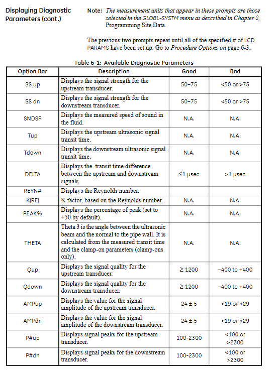
diagnostic parameters
Signal strength SS up/dn: 50-75 is normal
Signal quality Q up/dn: ≥ 1200 is normal
The amplitude AMP up/dn: 24 ± 5 is normal
Time difference Delta: ≤ 1 μ s is normal
Component replacement
fuse
AC: 0.25A slow melting
DC: 2.0 A slow melting
LCD/keyboard: Power off, remove cover, unplug and plug cables for replacement
Program EPROM (U4): Anti static, diagonally aligned notch press in
Warranty and Service
Warranty period: 1 year for both electronics and sensors
Not covered: fuses, batteries, misuse, non-standard accessories
Repair process: Apply for RA number → Prepay shipping fee → Factory inspection → Free warranty/paid repair
Software support
**PanaView ™** Support:
Serial port connection and multi instrument management
Read/draw/save sensor signals
Remote programming, cumulative reset, site file management
Real time data display and recording
Key questions and answers
Question 1: What are the requirements for the core straight pipe section of AT868 sensor installation? Why?
Answer: The installation of sensors must meet the requirements of a straight and undisturbed pipe section with an upstream diameter of ≥ 10 times the pipe diameter and a downstream diameter of ≥ 5 times the pipe diameter, and avoid turbulent sources such as valves, elbows, and reducers. This is to ensure a fully developed flow field, ensure the accuracy of ultrasonic flow measurement reaches ± 0.5%~2%, and avoid signal distortion and reading deviation caused by eddies, gas-liquid two-phase, and disturbances.
Question 2: What order should be followed to troubleshoot the E1 low signal error in AT868?
Answer: The order of investigation is:
Check whether the sensor cable is damaged, the shielding grounding is good, and the length difference is compliant
Confirm that the positive and negative terminals (red SIG+, black RTN -) of the sensor wiring are correct
Clamp type inspection of coupling agent and pipeline cleanliness, insertion type inspection for leakage/corrosion
Verify the accuracy of CHx PIPE pipeline parameters (outer diameter, wall thickness, material)
Enter the diagnosis to check the SS signal strength. If it is below 50, replace the sensor
Question 3: What are the standard procedures and accuracy requirements for AT868 analog output calibration?
Answer: Standard process:
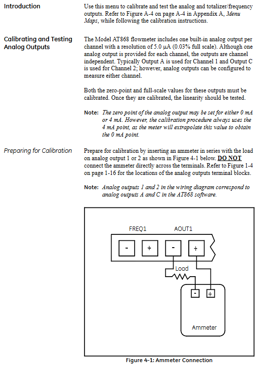
Connect the ammeter in series and enter CALIB → SLOT0 → A/C
Calibrate the low point of 4 mA and store it
Calibrate 20 mA high point, store
Perform a 50% range linear test to verify the output of 12.000 mA
Accuracy requirement: Calibration point error ≤ ± 0.005 mA, and full range linearity must meet this requirement before use.