Mitsubishi GOT2000/GOT1000 series serial communication unit
Product Overview
This document is the user manual for the Mitsubishi GOT2000/GOT1000 series serial communication module, applicable to three models: GT15-RS2-9P, GT15-RS4-9S, and GT15-RS4-TE, used for expanding serial communication between touch screens and FA devices.
Core Performance Specifications
Model Interface Type Connector Maximum Transmission Distance 5VDC Consumption Current
GT15-RS2-9P RS-232 D-sub 9-pin (male) 15m 0.29A
GT15-RS4-9S RS-422/485 D-sub 9-pin (female) 1200m 0.33A
GT15-RS4-TE RS-422/485 terminal block 1200m 0.3A
Communication speed: 115200/57600/38400/19200/9600/4800bps
Synchronization method: asynchronous
Verification methods: parity check, sum check
Weight: 0.09kg
Software requirement: GT Designer 2 Version 2.15R or above
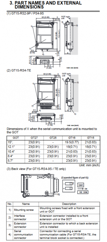
Components and Structure
Universal components
Installation screws: fixing module
Interface connector: Connect to GOT motherboard
Expansion connector: cascaded expansion unit
Serial port connector: external communication cable
Specialized components
GT15-RS4-9S/TE: DIP switch, used to switch the built-in 100 Ω terminal resistor
GT15-RS4-TE: Terminal socket, suitable for 0.08-1.5mm ² cables
Installation steps
Module installation (universal)
Cut off all phase power supplies of GOT
Remove the cover plate of the GOT expansion unit
Insert the serial port module into the card slot
Tighten 2 installation screws with a torque of 0.36-0.48N · m
Apply anti-static stickers when not expanding; Keep the connector cover when expansion is required
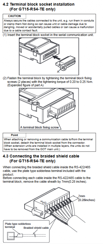
Terminal block installation (GT15-RS4-TE only)
Insert the terminal socket into the module
Tighten the fixing screw with a torque of 0.20~0.25N · m
Shielded wire wiring (GT15-RS4-TE only)
Stripping length: 7mm
Connect the braided shielding layer using plate type crimping terminals
Wiring screw torque: 0.5~0.6N · m
Safety and wiring precautions
Installation Warning
Before installation/disassembly, all power sources must be cut off, otherwise there may be malfunctions or electric shock
Do not disassemble or modify modules
Release human static electricity before operation
Prevent debris, wires, and other foreign objects from entering the machine
Wiring specifications
Separate communication cables from main circuit/power lines * * ≥ 100mm * * to avoid interference
The cable must be fixed to prevent poor contact caused by pulling and pulling
The connector must be securely plugged in to ensure a reliable connection
Accessories List
Model standard accessories
GT15-RS2-9P module, screw kit, instruction manual
GT15-RS4-9S module, screw kit, magnetic ring, instruction manual
GT15-RS4-TE module, screw kit, terminal block, shielded crimping terminal, instruction manual
Compliance and Environmental Protection
Compliant with CE, EMC, and low voltage directives
Compliant with China RoHS: Only the circuit board contains lead, all other components meet the standard
Applicable standards: GB/T15969.2, SJ/T11364
Key questions and answers
Question 1: What are the core differences in interface and transmission distance among the three modules?
answer:
GT15-RS2-9P: RS-232 interface, D-Sub 9-pin (male), maximum distance of 15m.
GT15-RS4-9S: RS-422/485 interface, D-Sub 9-pin (female), maximum distance 1200m.
GT15-RS4-TE: RS-422/485 interface, terminal block wiring, maximum distance of 1200m, suitable for on-site wiring.
Question 2: What are the key operations and torque requirements that must be followed when installing a serial port module?
answer:
The installation/removal of GOT and PLC power must be completely cut off.
The torque of the screws for installing the module body is 0.36-0.48N · m.
GT15-RS4-TE terminal block fixed torque: 0.20~0.25N · m.
Terminal wiring torque: 0.5~0.6N · m.
Anti static stickers must be affixed when not cascading expansion.
Question 3: What is the function of the DIP switch between GT15-RS4-9S and TE? How to set up?
Answer: DIP switch is used for RS-422/485 terminal resistance switching:
Switches 1 and 2 are both ON: use the built-in 100 Ω terminal resistor.
Switches 1 and 2 are both OFF: Use an external terminal resistor.
This setting is only available for GT15-RS4-9S and GT15-RS4-TE, and GT15-RS2-9P does not have this switch.