ZF Marine MM9000 ClearCommand Marine Propulsion Control System
System Overview
ClearCommand is a ZF marine propulsion electronic control system that provides integrated control of throttle, clutch, and towing valves for leisure and light commercial vessels. A single processor corresponds to a single engine/clutch, and dual propellers require two processors to communicate and collaborate through serial ports.
Applicable models: covering full configuration of mechanical/electronic throttle, servo/solenoid clutch, mechanical/solenoid drag
Control station: Standard up to 5, expandable to 9 through Station Expander
Power supply: 12/24VDC, working voltage 8~30VDC, continuous current 10A
Core advantages: single pole control, disturbance free switching between stations, safe commutation delay, dual propeller synchronization, precise towing control
Hardware model and configuration
Six processors correspond to different propulsion structures:
Model, throttle type, clutch type, towing type
9120 mechanical (servo) solenoid valve none
9121 mechanical (servo) solenoid valve servo
9122 mechanical (servo) solenoid valve solenoid valve
9210 electronic servo none
9211 electronic servo
9221 electronic solenoid valve servo
Operation function
Basic Operations
Power on self-test: idle+neutral, prompt sound indicating no control authority
Seize control: Press the switch button in neutral for 0.5 seconds, and the red light will remain on
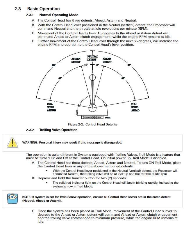
Control logic: * * 15 ° * gear shift, * * 65 ° * * linear acceleration
Advanced Mode
Warm up mode: Long press the neutral switch button → push forward, the red light flashes slowly, and the clutch remains in neutral
High and low idle: High idle maximum * * 20% * * throttle, warm-up automatically activated
Single stick mode (double paddle): Either stick is set as the main stick, the green light is on, and the single stick controls both machines
Engine synchronization: Wait for throttle/active synchronization, constant green light indicates synchronization completion
Proportional delay commutation: prevents commutation shock, adjustable delay from 0 to 99 seconds
Drag Mode
Enable: Press and hold the switch button in neutral for 2 seconds, and the red light will flash rapidly
Gear: 20/35/45/55 ° four speed drag range, throttle limit 10~75%
Installation specifications
Processor installation
Location: Dry place in the engine compartment, away from high temperature/strong magnetic field ≥ 1.2m, anti vibration installation
Grounding: 12AWG cable to ship grounding bar
Installation of control head
Waterproof: 400/MC2000 bottom protection, 700 series fully waterproof
Journey: Full travel without interference before and after
Wiring and mechanical connections
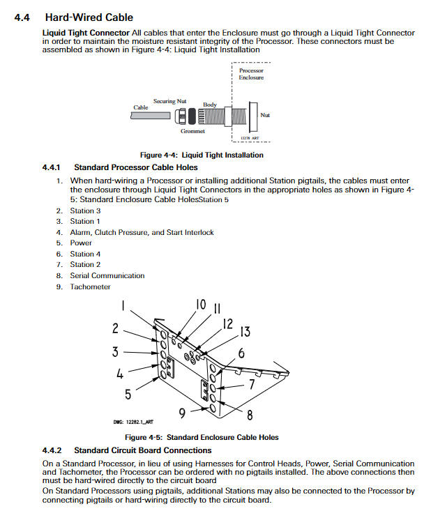
Wiring harness: shielded wire, fixed every 45cm, anti reverse insertion of connectors
Push pull cable: 33C type, length ≤ 6m, bending radius ≥ 25cm, total bending<270 °
Setting and Debugging
Setup method
Interface: 4-digit 7-segment LED, 4 buttons (left/right/up/down)
Enter settings: Simultaneously press and hold the left and right keys until flashing
Save: Simultaneously press and hold the left and right keys until the flashing stops
Core Function Code
System: A0 processor recognition (1-5), A1 engine count (1-5), A2 single pole mode, A3 station expansion
Throttle: E0 type, E1 neutral throttle, E2 minimum, E3 maximum, E6 high idle, E7 synchronous
Clutch: C0 pressure interlock, C2 proportional delay, C3 delay time, C5 direction
Dragging: L0 enabled, L2 minimum pressure, L3 maximum pressure, L4 oil threshold
Experimental verification
Mooring test: control, start interlock, stop switch, push-pull cable, high idle speed
Navigation test: full speed setting, synchronization, proportional delay, towing pressure calibration
Record: Fill in the F-226 test report and retain the parameters
Maintenance and upkeep
Cycle: Annual comprehensive inspection
Inspection items: Corrosion of control head terminals, connection of processors, damage to wiring harnesses, tightening of push-pull cables, power supply voltage
Power supply: The battery voltage is measured every 3 months, with 12V fully charged at 12.6-12.8V and 24V fully charged at 25.2-25.6V
Fault diagnosis
Diagnostic menu (H0)
Real time viewing: battery voltage, speed frequency, joystick position, switch key status, servo feedback, software version
Sound alarm (Class 7)
Slow intermittent sound: No control when powered on
One long and three short: joystick signal exceeds range
Long tone: Program shutdown/low voltage
5-second long tone: serial communication lost
fault code
Coverage: servo stalling, solenoid valve failure, low pressure, communication abnormality, gear failure
Key issues
Question 1: What are the two types of engine synchronization for twin propeller ships? What conditions do they each rely on?
answer:
Waiting for throttle synchronization (open-loop): Only controls the throttle stroke to be consistent, without the need for a speed sensor, relying on the consistency of push-pull cables/electronic signals.
Active synchronization (closed-loop): To adjust the throttle compared to the actual speed, a speed sensor must be installed with an accuracy of ± 1%. If the sensor signal is lost, it can be switched back to the throttle.
Question 2: What is the difference between the function of Proportional Pause and the three modes?
Answer: The function is to slow down to idle and delay during reversing, protecting the gearbox and transmission system. Three modes:
C2=00 gear shift delay: maintain the original gear position, switch direction after delay
C2=01 Neutral Delay: Switch to neutral and change direction after delay
C2=02 Fixed Neutral Delay: Fixed delay time, mostly used for bow side pushing
Question 3: What are the four conditions that must be met if the system cannot start the engine (start interlock takes effect)?
Answer: It must simultaneously satisfy:
The DC power supply of the processor has been connected
A control station has seized control
The control lever is in neutral position
The start interlock relay has been closed