Pro face GP-2400/2500/2600 Series Operating Manual
Product Overview and Safety Standards
The GP-2400/2500/2600 series is the new generation of modular human-machine interface from ProFi, which supports Ethernet, CF card, and audio output without the need for expansion modules, improving integration and usability.
Security level: Front panel protection IP65f, NEMA Type4X/12
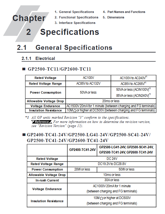
Power supply specifications:
DC model: DC24V (19.2~28.8V)
AC model: AC100~240V (85~265V)
Core taboos:
The emergency stop button must be implemented in hardware, and touch screen software buttons are prohibited
Backlight failure automatically disables touch to prevent misoperation
Explosion proof environment requires cutting off the power supply before plugging in and out the module
Hardware specifications (key parameters)
1. Electrical and Environmental
Project parameters
Working temperature 0~50 ℃
Working humidity 10~90% RH (no condensation)
Power consumption: DC type ≤ 50W, AC type ≤ 85VA
Shock/vibration complies with IEC61131-2
Insulation resistance ≥ 10M Ω at DC500V
2. Display and Touch
Series Display Type Resolution Touch Accuracy
GP-2400 TFT color 640 × 480 32 × 24
GP-2500 TFT/STN/Monochrome 640 × 480 32 × 24
GP-2600 TFT Color 800 × 600 40 × 30
3. Interfaces and extensions
Standard interfaces: Ethernet (10BASE-T), RS-232C/RS-422, printer, CF card, audio, tool port
Scalability: Maximum 4608 I/O points, supports remote I/O rack
CF card: Supports 64MB~512MB, used for data backup, recipe, log, and screen transfer
Installation and wiring
Installation requirements
Panel thickness: 1.6~10mm
Surrounding distance: ≥ 100mm, ensuring heat dissipation
Fixed: comes standard with 4 buckles and a torque of 0.5N · m
Wiring specifications
Grounding: independent grounding, grounding resistance * * ≤ 100 Ω * *, wire diameter ≥ 2mm ²
Power supply: power-off wiring, separate strong current and signal wiring
CF card: power off insertion and removal, operation after the indicator light goes out
Data transmission
Supports three transmission methods to meet on-site deployment requirements:
Serial transmission: via GPW-CB02 cable, with a maximum speed of 115.2kbps
Ethernet transmission: supports IP settings, remote download of screens and systems
CF card transfer: Implementing batch deployment of multiple HMIs through Memory Loader Tool
Upload: HMI → CF card (backup all data)
Download: CF Card → HMI (Recovery/Batch Deployment)
Operation mode
1. Offline mode (OFFLINE)
Entry method: Click on the top left corner within 10 seconds of startup, or enter through the menu
Core functions: initialization, self diagnosis, data transfer, memory formatting
2. Running mode (RUN)
Automatically enter upon startup, display configuration screen, and communicate in real-time with PLC
Support online modification, alarm display, data recording, and sound prompts
Initialization configuration (core item)
System environment: standby time, touch beep, password (0~9999)
I/O settings: Serial port baud rate (2400~115200bps), printer, touch calibration
PLC settings: 1:1/n:1 connection, station number (0~15), system area address, Ethernet IP
Memory initialization: password 1101, clear SRAM data, retain system and clock
Clock setting: Monthly error * * ± 65 seconds * *, lithium battery backup life of 10 years (below 40 ℃)
Self diagnostic function
Covering full hardware detection and quickly locating faults:
Character/display pattern, touch screen, internal Flash, frame buffer
Serial port, printer, CF card, sound, extended serial port
Each test returns OK/NG to guide maintenance
Troubleshooting (high-frequency issues)
Common causes and solutions of fault phenomena
No display power error, backlight burned out, screen turned off. Check power supply, replace backlight, clear system area shutdown command
PLC communication line sequence error, baud rate mismatch, station number conflict rewiring, calibration parameters, unique station number
Touch failure, backlight failure, disabling, calibration error, peripheral interference, backlight replacement, recalibration, disconnection of peripheral devices
The startup beep system program is damaged, the CF card boot file is lost, and the system is forcibly downloaded. The CF card file is repaired
Maintenance and upkeep
Cleaning: Neutral detergent, no organic solvents, sharp objects
Sealing gasket: replaced annually to ensure IP65f protection
Backlight replacement: lifespan of 50000 hours, power-off operation, model matching
Battery: cannot be replaced by oneself, replaced by the agent to prevent explosion
Key issues
Question 1: How can GP series HMI achieve batch deployment of multiple devices through CF cards?
Answer: First, complete the configuration and settings on an HMI, and upload the complete system, screen, protocol, and data to the CF card through the offline mode CF Memory Loader Tool; Insert the CF card into another HMI, toggle DIP switch 1 or start it through the CF BOOT menu, and download to batch copy without connecting to each computer.
Question 2: What is the most likely reason and troubleshooting steps for the touch screen not responding but the screen is on?
Answer: The most likely reason is that the backlight burns out and triggers safety protection, which is automatically disabled by touch. Troubleshooting steps: ① Check if the status light is orange → If it is, there is a backlight fault; ② Enter offline mode to test touch → normal is the protection mechanism; ③ Enable temporary recovery of USE TOUCH PANEL AFTER BACK LIGHT BURNOUT during initialization, and replace the backlight as soon as possible.
Question 3: What order should be followed to troubleshoot the PLC communication error “PLC NOT Replying”?
Answer: Check in order from hardware to parameters: ① Check that the PLC power is turned on; ② Confirm that the RS-232C/422 cable is wired correctly; ③ Verify that the baud rate, data bits, checksum, and stop bits of HMI and PLC are completely consistent; ④ Check that the 1:1/n:1 mode, station number, and system area address are set correctly; ⑤ Start the PLC first and delay for 2-3 seconds before starting the HMI to ensure the correct startup sequence.