Kepco BOP Bipolar Power Supply Operating Instructions
Product positioning and series models
Kepco BOP is a fully dissipative linear bipolar power supply, covering three power levels of 100W/200W/400W, used for high-precision testing and power driving.
Model and Power Correspondence Table
Typical power model output range
100W BOP 50-2 ±50V / ±2A
200W BOP 100-2 ±100V / ±2A
400W BOP 20-20 ±20V / ±20A
Core working principle
Dual mode control: voltage mode constant voltage, current mode constant current, choose one to work.
Bipolar output: capable of outputting * * ± voltage/± current * *, supporting source/sink bidirectional current.
Automatic switching: When the amplitude limit is reached, it automatically switches from control mode to amplitude limit mode.
Two channel preamplifier: voltage/current channel independent preamplifier, supporting direct external signal drive.
Electrical specifications
input
Voltage: 115V/230V AC switchable, 50~65Hz
Protection: Front panel circuit breaker, full voltage effective
environment
Working temperature: 0~+55 ℃
Storage temperature: -40~+85 ℃
Cooling: Built in fan exhausts air backwards
output performance
Voltage/current: ± 100% full range continuously adjustable
Ripple noise:<30mV rms,<0.1%
8-hour temperature drift: 0.01%
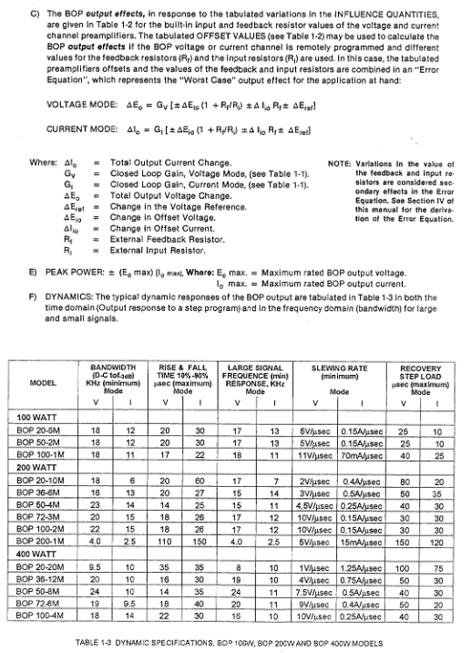
Bandwidth: DC~several hundred kHz (different models)
Pressure swing rate: up to 0.5A/μ s, 10V/μ s
Operation mode
1. Local operation (front panel)
Mode switch: Select voltage/current
Adjustment knob: Set output value
Limiting knob: independently set * * ± voltage, ± current * * limiting knob
Header: Zero center table, accuracy * * ± 2% F.S**
2. Remote operation
Signal: ± 10V control full range output
Interface: Rear PC-12 50 pin programming connector
Support: direct control of potentiometers, resistance boxes, and signal sources
Remote error detection: compensating for line voltage drop for higher accuracy
3. Digital control (recommended)
Module: BIT 4886 16 bit card insertion
Bus: GPIB (IEEE488.2), RS232
Protocol: SCPI, CIIL
Communication parameters: 9600 baud, 8N1
System Expansion
Series connection: master-slave mode, voltage superposition, maximum isolation of 500V
Parallel connection: master-slave mode, current sharing
Linkage protection: If one device fails, all devices will shut down
Load and stability
Resistive load: optimal performance, no oscillation
Inductive load: 0.1~1 μ F parallel capacitor is required to suppress oscillation if>0.5mH
Capacitive load: Allow * *<0.2F**
Power outage protection: It is recommended to install UPS and reset the output to zero before shutting down
Installation and wiring
Grounding: Class I equipment must be reliably grounded
Output: Choose between front and rear terminals, cannot be used simultaneously
Sensing: The sensing terminal must be on the same side as the output
Prohibition: The output terminal must not be directly grounded to avoid damage
Calibration and maintenance
Internal calibration: ± 10V reference, zero point of ammeter, linearity of optocoupler
Calibration tools: digital multimeter, oscilloscope
Maintenance: Regularly clean the dust and keep the air duct unobstructed
Security and Certification
Standard: EN61010-1:2001, LVD low voltage command
Protection: Comprehensive protection against overcurrent, overvoltage, overtemperature, and power failure
Identification: Output end with high voltage danger warning
Key issues
Question 1: What is the core difference between voltage mode and current mode of BOP power supply? What loads are suitable for each?
answer:
Voltage mode: outputting a constant voltage, the current is determined by the load, and automatically limiting the amplitude when reaching the current limit value; Suitable for loads such as resistors, instruments, amplifiers, etc. that require stable voltage.
Current mode: outputting a constant current, voltage determined by the load, and automatically limiting when the voltage limit is reached; Suitable for loads such as coils, motors, inductors, etc. that require stable current.
Question 2: When driving a large inductive load, BOP is prone to oscillation. Which two reliable solutions are provided in the manual?
answer:
Connect 0.1-1.0 μ F capacitors in parallel at both ends of the load.
Parallel RC series network (R=100~500 Ω, C=0.1~0.5μF)。
High power models can be upgraded to ML version to eliminate wide range inductive load oscillation.
Question 3: How can BOP achieve multi platform expansion? What should be noted for series and parallel connections?
answer:
Series connection: Set all to voltage mode, controlled by the main unit, followed by the slave units, output voltage superposition, total voltage not exceeding 500V isolated withstand voltage.
Parallel connection: All are set to current mode, controlled by the main unit, followed by the slave units, output current is evenly distributed, and the cables need to be thick enough.
Common requirement: master-slave linkage protection must be used, and all faulty devices must be shut down.