CAREL PGD graphic display handheld device
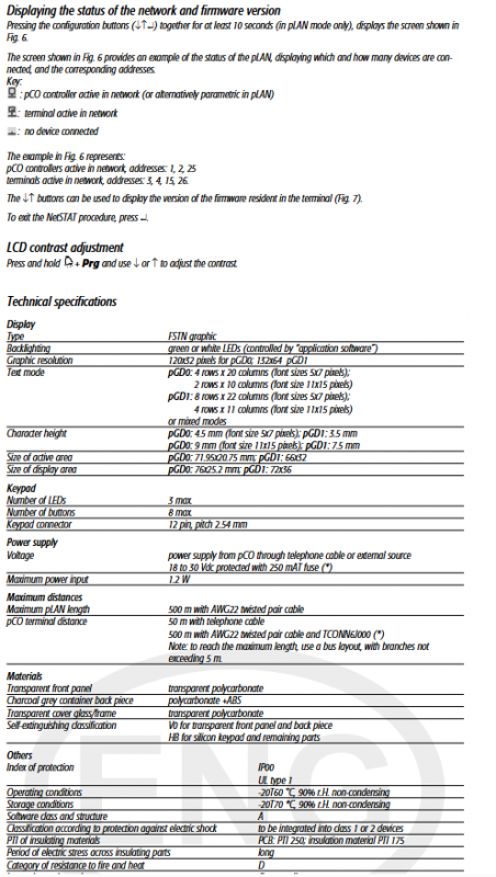
The technical manual for CAREL PGD series graphic display handheld device (PGD0000N00/PGD1000N00/PGD1000NW0) is compatible with pCO control system, providing two resolutions of 120 × 32 and 132 × 64, green/white backlight options, supporting external 8-key keyboard+3-channel LED, connected to pCO motherboard through RJ12 telephone line, configurable address, dedicated/shared terminal, network status monitoring, working temperature * * -20~60 ℃, maximum communication distance of 500 meters * *, suitable for graphic monitoring and parameter setting of industrial equipment such as refrigeration and air conditioning.
Product model and specifications
Model Resolution Backlight Appearance Openings
PGD0000N00 120 × 32 pixel green 78 × 30mm
PGD1000N00 132 × 64 pixel green 74 × 39mm
PGD1000NW0 132 × 64 pixel white 74 × 39mm
Core Features
system compatibility
Fully compatible with pCO controllers, replacing old PCOI/PCOT controllers
The program is stored on the pCO motherboard, and the handheld device does not require separate software
Display and Font
Supports two fonts: 5 × 7/11 × 15 pixels
Icon graphical display, supporting international characters
Button and LED
The body has no buttons or LEDs
External membrane keyboard (up to 8 keys), LED indicator lights (up to 3)
Environment and Electrical
Working temperature: -20~60 ℃
Power supply: 18~30VDC, maximum power 1.2W
Communication line length: pLAN up to 500 meters, direct connection to pCO up to 50 meters
Installation and wiring
Mechanical Installation
Installed on the inside of the metal panel, with a panel thickness of ≥ 2mm
Hole size:
PGD0:78×30mm
PGD1:74×39mm
Keyboard flat cable opening: ≥ 40 × 10mm
electrical connection
Keyboard interface: 12 pins, pay attention to the polarity of Pin1 (marked with D)
Communication interface: RJ12 telephone line (S90CONN00) * connected to pCO motherboard
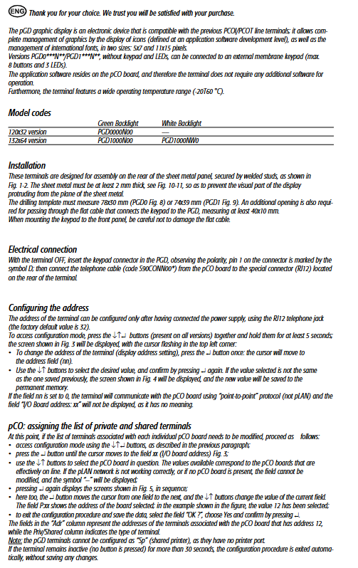
Parameter configuration
Address setting
Factory default: 32
Enter configuration: Long press ←↑↵ 5 seconds
Address=0: Enable point-to-point communication (disable pLAN)
Dedicated/shared terminal configuration
Configure the pCO motherboard address (xx) and bind it to the controller
Cannot be configured as a shared printer (Sp)
Network and Debugging
Long press ←↑↵ 10 seconds: View NetSTAT network status
Long press+Plg+←/↑: Adjust LCD contrast
Can view firmware version and online device list
Fault prompt
Meaning of fault information
I/O Board xx fault corresponds to offline/faulty pCO motherboard
NO LINK handheld device did not receive network signal
Key issues
Question 1: What is the difference between setting the PGD controller address to 0 and a regular address? What scenarios are they used in?
answer:
Address=0: Using point-to-point protocol, not connected to pLAN network, only communicating with directly connected pCO, suitable for single machine control.
Address=1~63: Using pLAN network protocol, multiple handheld devices and controllers can be networked, suitable for centralized monitoring systems.
Question 2: What are the wiring methods and maximum distances between the PGD controller and the pCO motherboard?
answer:
Direct connection method: using RJ12 telephone line, with a maximum distance of 50 meters.
PLAN networking method: using AWG22 shielded twisted pair, maximum distance of 500 meters, branch ≤ 5 meters.
Question 3: The PGD handheld device itself does not have buttons. How to set parameters, modify addresses, and adjust contrast?
answer:
Address/Network Configuration: Use the built-in combination key ←↑↵ on the handheld device to enter.
Contrast adjustment: Long press+Prg with ←/↑ adjustment.
Daily operation: An 8-key membrane keyboard can be connected externally to achieve complete operation.