OMRON SYSMAC C-series/CVM1/CV series analog I/O units
Basic Information
Applicable products: Omron C-series, CVM1, CV series PLC with analog input unit (AD) and analog output unit (DA)
Core purpose: To achieve analog-to-digital (A/D) and digital to analog (D/A) conversion between PLC and on-site sensors/actuators, and to process analog signals such as temperature, pressure, flow rate, voltage, and current
Document audience: Electrical technicians involved in the design, installation, and operation of FA systems
Core specifications: including safety warnings, usage environment, compliance with EC directives (EMC/low voltage directives), disclaimer and warranty clauses
Overall architecture and core unit classification
The manual is divided into 9 chapters based on input unit → output unit, covering 11 core analog units and divided into two categories:
1. Analog input unit (AD, 6 types in total)
Basic models: 3G2A5-AD001~AD005 (2-point input, 12 bit resolution), 3G2A5-AD006~AD007 (4-point input, 10 bit resolution)
Mid end model: C500-AD101 (8-point input, 12 bit, mean/peak hold/break detection/scaling)
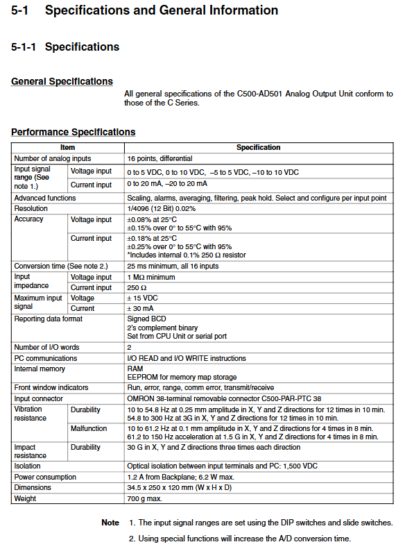
High end model: C500-AD501 (16 point differential input, 12 bit, built-in processor, scaling/filtering/averaging/alarm/EEPROM storage)
2. Analog output unit (DA, 5 types in total)
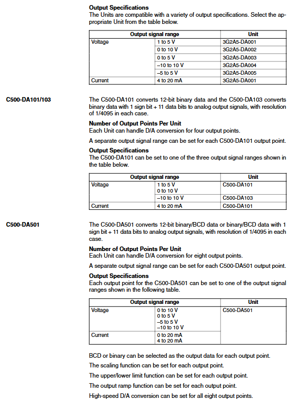
Basic models: 3G2A5-DA001~DA005 (2-point output, 12 bit resolution)
Mid end models: C500-DA101 (4-point output, 12 bit), C500-DA103 (4-point bipolar voltage output)
High end model: C500-DA501 (8-point output, 12 bit, scaling/ramp output/upper and lower limit limits/EEPROM storage)
Core Technical Specifications (General)
Resolution: Mainstream 12 bit (1/4095), AD006/007 is 10 bit (1/1023)
Signal range
Voltage: 0~5V, 0~10V, ± 5V, ± 10V, 1~5V
Current: 0~20mA, 4~20mA, ± 20mA
Conversion speed: fastest single channel 2.5ms, highest 16 channel 25ms
Data format: binary (complement), BCD code, switchable by channel
Isolation: Optoelectronic isolation between input/output and CPU, withstand voltage of 500VAC
Installation: Compatible with CPU rack, extended I/O rack, SYSMAC BUS/2 slave rack (some units do not support BUS slave rack)
Key functional characteristics
1. Core functions of input unit
Basic conversion: Analog signal → 12/10 digit digital quantity
Advanced features (AD101/AD501):
Mean calculation, peak holding, wire breakage detection, range scaling, upper and lower limit alarms, digital filtering
Storage: AD501 has built-in EEPROM, which saves parameters in case of power failure
Mode: Supports 2-word/4-word working mode, adapted to different PLC instructions
2. Core functions of output unit
Basic conversion: digital quantity → analog signal
Advanced features (DA501):
Range scaling, output ramp (anti mutation), upper and lower limit limiting, power-off output holding/zeroing
Configuration: Each channel independently sets the signal type and supports bipolar voltage output
Installation, wiring, and configuration specifications
1. Installation requirements
Environment: No direct sunlight, no corrosive/flammable gases, dust-proof and moisture-proof, anti vibration and strong electromagnetic interference
Grounding: Grounding resistance ≤ 100 Ω, must be reliably grounded
Power off operation: Before installation, dialing, and wiring, the PLC power must be cut off
2. Wiring rules
Cable: Shielded twisted pair must be used, and analog and high-voltage lines must be routed in separate slots
Terminal: voltage/current input/output differentiated wiring, unused terminal short circuited to prevent interference
Current input: Short circuit the designated terminal to match a 250 Ω input impedance
3. Configuration method
Dial switch: Set signal range and working mode (2/4 characters)
Software configuration: Set parameters and function switches through PLC instructions (READ/WRIT/MOV)
Parameter storage: High end units can be written into EEPROM and automatically loaded upon startup
Communication and Programming
1. Communication method
2-Word Mode: Read and write at high speed using Read/WRIT specific instructions, supporting batch data transfer
4-word mode: Use MOV universal instructions to adapt to PLC/slave racks that do not support dedicated instructions
Address allocation: Each unit occupies 2-4 CIO/IR words and is automatically allocated according to the slot
2. Core instructions
Input unit: Read converted data, WRIT write configuration parameters
Output unit: WRIT write output value, MOV single word control
Status judgment: Monitor communication through flag bits (busy flag, complete flag, error flag)
3. Programming Examples
The manual provides a complete ladder diagram program, covering:
Basic A/D and D/A conversion
Scaling, alarm, filtering, and ramp function configuration
Peak holding, wire breakage detection, parameter writing to EEPROM
Safety and usage taboos
Live prohibition: It is strictly prohibited to disassemble or assemble cabinets, touch terminals, dial codes, or connect wires when powered on
Overload protection: It is strictly prohibited to input/output beyond the range to prevent unit burnout
Application restrictions: Cannot be used in life safety scenarios such as nuclear control, aviation, medical, and in vehicle applications
Fault handling: Determine the fault through the RUN/ErrOR/RANGE indicator lights, and after reporting an error, turn off the power for troubleshooting
EC compliance: The CV series needs to be installed inside the control cabinet, and the power supply meets the requirements of double insulation