Operation and Maintenance Instructions for HMS Anybus Communicator Communication Gateway
Operation and Maintenance Manual for DME Systems Custom Edition HMS Airbus Communicator (ABC3007) Communication Gateway, Core Used for Serial Port (RS-232/485) ↔ EtherNet/IP protocol conversion for on-site maintenance scenarios such as device replacement, configuration backup, log export, and troubleshooting.
Equipment Overview
1. Core functions
Serial port (RS-232/485) ↔ EtherNet/IP protocol converter, enabling serial devices to connect to industrial Ethernet.
2. External interfaces and components (key)
Power interface: 12-30 VDC
Configuration port: used for debugging
7-pin serial port: RS-232/485
Dual Ethernet ports (X1, X2)
Security Switch: Lock/Unlock Configuration
Reset button: Factory reset
Status LED, Ethernet LED
DIN rail buckle
3. Electrical connection
Power supply: 12-30 VDC (Pin1: power supply, Pin2:GND)
Ethernet: RJ45 (X1, X2)
Serial port: RS-232/485 (7-pin)
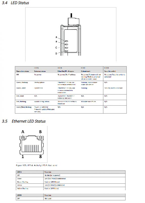
Status indicator light (essential for on-site diagnosis)
1. Run LED (D)
Evergreen: Running normally, EtherNet/IP connected
Green and red flashing: Start self-test/fault
Extinguish: No electricity
2. Safety switch LED
Always on: Safety switch locked (configuration cannot be changed)
Extinguish: Unlock (configurable)
3. Ethernet LED (A)
Yellow Flash: 100M Activity
Always on: Link connected (10M)
Safety precautions
Must first read DME Safety Manual A1678-ED
Danger/Warning/Attention Level 3 Risk Warning
Waste needs to be treated environmentally, contact DME for guidance
Core Operating Procedures
1. Replace equipment configuration (must see for replacement parts)
Goal: Import the old configuration into the new gateway
New device powered on
Set PC to 192.168.0. x network segment
PC network port → Device X1 network port
Browser Access: 192.168.0.10
Enter: Files&Firmware → Import
Load backup configuration file → Select Import Settings
Click Apply to write
Enter EtherNet/IP → Set IP and subnet → Apply
Reconnect X2 network cable completed
2. Configure backup (daily maintenance)
Connect to X1 network port and access 192.168.0.10
Files & Firmware → Export
Save configuration file to computer
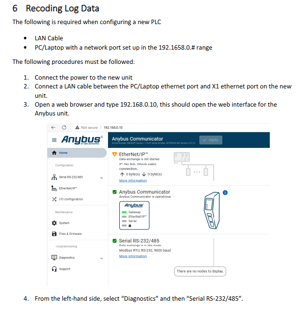
3. Serial port logging (debugging faults)
Used to capture serial port data and troubleshoot communication issues
Connect X1 and access 192.168.0.10
Enter Diagnostics → Serial RS-232/485
Start recording → Pause stop
Export as. xlsx file
Environment and Storage
Storage: Dry and clean, 5-25 ° C
Power supply: 12-30 VDC
Protection: Industrial DIN rail installation