BECKHOFF CX51x0 Series Embedded PC Hardware Manual
Product Overview
Product positioning and model division
CX51x0 is a modular DIN rail mounted embedded PC based on Intel Atom architecture, divided into three hardware models: CX5120, CX5130, and CX5140. The core differences are processor and memory:
|Model | Processor | Core | Memory|
|CX5120 | Intel Atom E3815 1.46GHz | Single Core | 2GB DDR3|
|CX5130 | Intel Atom E3827 1.75GHz | Dual Core | 4GB DDR3|
|CX5140 | Intel Atom E3845 1.91GHz | Quad Core | 4GB DDR3|
The entire series comes standard with fTPM 2.0 security chip, built-in 1-second supercapacitor UPS, dual gigabit Ethernet ports, 4-channel USB 2.0, DVI-I. It is equipped with CFast and MicroSD dual storage slots, and the memory cannot be expanded later.
hardware architecture
Chipset: CPU integrated graphics card, memory controller, paired with Intel i210 Gigabit Ethernet card, FPGA to implement E/K bus;
Bus system: PCIE bus carries network ports, serial interfaces FPGA; SATA docking with CFast, IDE docking with MicroSD;
Power supply: External 24VDC input, the whole machine is uniformly powered to the board and bus terminals through the power module.
System and software selection
Supporting operating systems: Windows Embedded Compact 7、Windows Embedded Standard 7 P、Windows 10 IoT Enterprise Each LTSB/LTSC version TwinCAT/BSD; WinCE has stopped security updates.
TwinCAT software: Supports TwinCAT 2/3 and can implement IEC 61131-3 standard PLC and multi axis motion control (electronic gears, flying saws, camshafts, etc.).
Naming convention: The suffix of the model distinguishes between the operating system and TwinCAT authorization. Different combinations are pre installed at the factory and cannot be replaced on site.
Standard configuration+optional interface
Standard built-in interface (factory standard)
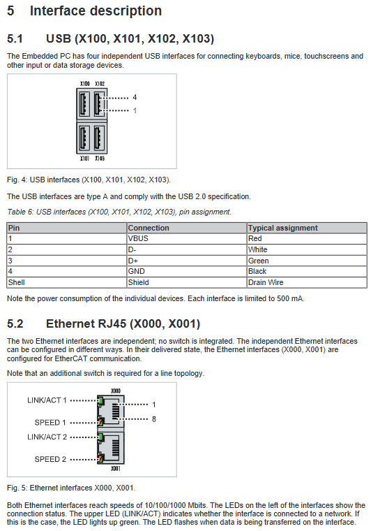
USB (X100~X103): 4-channel USB 2.0 Type-A, single port maximum 500mA, used for keyboard, mouse, USB flash drive, and peripherals.
Dual Gigabit Ethernet (X000/X001): Independent 10/100/1000M Ethernet ports with link/rate indicator lights, default for EtherCAT communication.
DVI-I (X200): Compatible with both digital and analog signals, with a maximum length of 5m and a maximum resolution of 1920 × 1200. It can be converted to a VGA monitor.
Original factory optional interface (only pre installed at the factory, not available for on-site installation)
There are a total of 10 types of expansion interfaces, covering video, serial port, audio, and mainstream fieldbus:
N010 (DVI-D): Pure digital video interface, maximum resolution 1920 × 1200;
N011 (DisplayPort): Integrated audio and video, up to 2560 × 1600, can be converted to DVI/HDMI;
N020 (audio): 3.5mm interface, including line input, microphone, line output (maximum 200mW), disabled in explosion-proof area;
N030 (RS232): 9-pin D-Sub, maximum 115k baud rate;
N031 (RS422/RS485): Optoelectronic isolation, supports multiple modes such as terminal resistance and echo, with a baud rate of 115k;
M112 (EtherCAT master), B110 (EtherCAT slave): RJ45 interface, supporting EtherCAT ring network redundancy;
M310/B310 (PROFIBUS master/slave): 9-pin interface, speed of 9.6k~12M;
M510/B510 (CANopen master/slave): 9-pin interface;
M930/B930 (PROFINET RT controller/device): dual RJ45 network ports.
Installation, wiring, and power on
Mechanical installation requirements
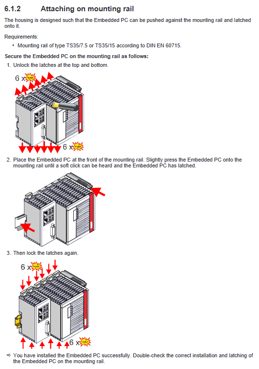
Installation rail: compatible with TS35/7.5 and TS35/15 standard DIN rails.
Installation posture: Only horizontal installation is allowed; A 30mm ventilation gap must be reserved above and below the equipment to ensure heat dissipation; The ambient temperature range is -25 ℃~+60 ℃.
Anti vibration: Additional fixed brackets need to be installed in vibration scenarios to prevent equipment from slipping.
Terminal installation taboos: Passive EtherCAT terminals (such as EL9195) should not be installed directly against the power supply end, as it can interfere with E-bus signals. Passive terminals can be identified in TwinCAT.
Storage card disassembly and assembly (CFast/MicroSD)
Operating premise: The entire machine must be powered off and hot plugging is prohibited;
Disassembly and assembly method: Press type pop-up structure, push in the card and hear the sound of the buckle to confirm installation in place;
Requirement: Only use Beifu industrial grade storage cards, with wide temperature range and high erase life. Third party cards are prone to damage and data loss.
power wiring
Input specifications: External 24V DC, voltage fluctuation allowed -15%~+20%.
Terminal differentiation:
Us 24V: provides power for embedded PCs and bus systems;
Up 24V: Provides power to bus terminals, sensors/actuators.
Cable specifications: wire diameter 0.5~2.5mm ² (AWG20~14), stripping length 8~9mm;
Safety regulations:
Power off wiring, short circuit 0V to protective ground (in accordance with EN 60204-1 PELV standard);
UL requirement: The front-end should be equipped with a maximum 4A fuse or use NEC Class2 isolated power supply;
Power off operation: Only disconnect the 24V positive pole, and it is strictly prohibited to disconnect the ground wire to avoid damage to the equipment caused by stray currents.
Power on judgment: Both power indicator lights are green, indicating normal power supply.
Power on
Power on: After confirming that the wiring, terminals, and installation are correct, connect the external 24V power supply and the device will automatically start;
Shutdown: First, shut down the software and operating system normally, and then cut off the external power. It is forbidden to directly power off during operation to prevent data damage to the storage card.
System configuration and software operation
Operating system related configurations
Network configuration (Win7/Win10)
Network port recognition: The system device manager can distinguish between two gigabit network cards;
Jumbo Frames: Requires installation of the original Intel network card driver (which will uninstall the Beifu real-time driver), supports 4088/9014 byte frames, and is suitable for big data transmission;
NIC Teaming: Original factory drivers are also required to achieve link redundancy and automatic fault switching.
Real time driver recovery: Use the TcRteinstall.exe tool to reinstall the Beifu EtherCAT real-time driver.
Serial interface (N030/N031) configuration
There are two working modes for the serial port, which need to be switched in the BIOS. The two options cannot be mixed:
TwinCAT mode: BIOS is set to PCI mode, the serial port is hidden in the system device manager, and recognized as COM99 in TwinCAT;
Windows mode: BIOS set to ACPI mode, recognized as a standard COM port in the system, TwinCAT cannot be called.
Audio configuration (WinCE)
Turn on the audio device through the CX configuration tool, adjust the input and output volume and signal source.
Remote Management (Beckhoff Device Manager)
Access method: Same network segment browser access, old version uses HTTP (port 80), new version uses HTTPS (443);
Default account: username Administrator, password 1;
Function: View device temperature, load, fan, firmware, enable remote desktop (CE system), and use CERHOST tool to achieve remote control.
TPM security chip
The whole machine is equipped with fTPM 2.0 firmware level security chip, which is turned off by default; It needs to be enabled in BIOS and only supports 64 bit Win10 1809 and above versions for data encryption and tamper proof.
TwinCAT configuration and functionality
Device scanning: TwinCAT automatically identifies E-bus/K-bus terminals by searching and scanning CX51x0 through IP/hostname;
Serial port configuration: Select PCI device mode in TwinCAT to complete serial port parameter configuration;
EtherCAT cable redundancy: using dual network ports to build a ring network, automatic switching in case of cable failure, ensuring continuous communication;
Hardware watchdog: Call the FB-PcWatchdog-BAPI function block to automatically restart the device when the program freezes or the PLC stops.
Built in UPS (supercapacitor) in seconds
Functional Description
Built in supercapacitor, can maintain power supply for about 1 second after power failure, and can store up to 1MB of persistent data to prevent data loss during power failure; Only applicable to the main control, does not support K/E bus power supply.
Configuration points
BIOS: Enable SUPS function and set parameters such as charging delay and USB power failure;
Write filtering: When EWF/FBWF/UWF is enabled in the Win system, the TwinCAT startup directory needs to be added as an exception, otherwise data cannot be saved;
PLC programming: Call the FB_S-UPS_CX51x0 function block, supporting multiple modes: shutdown after saving data, data only, direct shutdown, status detection;
Data verification: Determine whether persistent data is loaded properly through system variables, and support calling backup files.
Fault diagnosis and indicator light description
Whole machine diagnostic LED
Meaning of indicator light status
The PWR power supply lights up green normally, and red/yellow briefly lights up during the startup phase
TC TwinCAT Running (green), Stopping (red), Malfunction/Collapse (yellow)
Red light flashes when reading and writing HDD CFast card
FB1/FB2 fieldbus status indicator light
Bus diagnosis
K-bus (bus terminal)
K-BUS RUN: Green light constantly on=communication is normal;
K-BUS ERR: The flashing red light indicates a fault. The fault code and location are distinguished by a flash start and two slow flashes. It supports more than ten types of faults such as terminal open circuit, register error, and configuration mismatch, and can be reset when powered off;
Software diagnosis: Read State state variables in TwinCAT, analyze bus errors, task asynchrony and other issues bit by bit.
E-bus (EtherCAT terminal)
L/A indicator light: off=not connected; Always on=Connected with no data; Flashing=normal data transmission.
Common faults and their solutions
The whole machine has no response: check the 24V power supply, fuses, and wiring;
Unable to boot: Check if the storage card is securely plugged in, if the system files are damaged, and if the BIOS settings are abnormal;
Bus communication abnormality: Check the terminals, circuits, and configurations by comparing the indicator lights.
Maintenance, disassembly, and scrapping
Regular maintenance and replacement of spare parts
Official recommendation for replacement cycle:
Motherboard battery, UPS battery, fan: 5 years;
CFast/MicroSD/SSD: 10 years;
Industrial hard drive: 5 years (shortened cycle in high temperature environment).
routine maintenance
Cleaning: After turning off the power, wipe the machine body with a soft damp cloth. Do not use high-pressure gas, corrosive cleaning agents, or hard tools; Keep the ventilation openings unobstructed.
Battery replacement: Power off the entire machine, replace the CR2032 3V button battery, and recalibrate the system time after replacement.
Anti static measures must be taken for all disassembly and replacement operations.
Dismantling and scrapping
Disassembly steps: Shut down the system → Cut off the power → Remove all cables → Unlock the DIN rail buckle → Remove the device;
Scrap: After disassembling the entire machine, electronic components are strictly recycled according to local electronic waste regulations and are prohibited from being discarded at will.
Summary of Core Technical Parameters
Power supply: 24V DC (-15%~+20%), CX5120 maximum power consumption 11W, CX5140 maximum 16W;
Environment: Operating at -25 ℃~+60 ℃, storage at -40 ℃~+85 ℃, humidity ≤ 95% (no condensation), IP20;
Immunity: Vibration, impact, EMC comply with corresponding EN standards;
Bus capacity: K-bus can accommodate up to 64 terminals (with an extension of 255), while EtherCAT supports 65534 terminals;
Display: The DVI-I/DP interface supports a maximum resolution of 2560 × 1600;
Protection certification: standard CE and UL; Optional explosion-proof certifications such as ATEX, IECEx, CCC, etc.