BECKHOFF EL600x/EL602x series EtherCAT serial port terminal module
Product Overview
Core functional positioning
EtherCAT bus to serial port terminal enables communication between PLC and RS232/RS485/425 peripherals such as frequency converters, instruments, barcode scanners, sensors, etc. It sends and receives data through EtherCAT process data/CoE read-write serial ports and supports mapping virtual COM drivers to Windows standard serial ports.
Classification and core differences of five modules
EL6001 (1-channel RS232)
Single channel RS232, full duplex, supports RTS/CTS hardware handshake;
Sending and receiving buffer: 864 bytes for receiving, up to 250 bytes for sending;
The baud rate is 1000~115200 (fully integer adjustable in the new firmware), and the cable length is up to 15m.
EL6021 (1-channel RS422/485)
Differential signal, full/half duplex optional, built-in standard bias resistor;
Twisted pair cables up to 1000m in length, with multi node communication in bus topology.
EL6021-0021 (dedicated RS485 for the middle section of the line)
High resistance bias resistor, to avoid level imbalance when multiple modules are connected in parallel on the bus, only installed at the middle point of the bus, with standard EL6021 terminals at both ends.
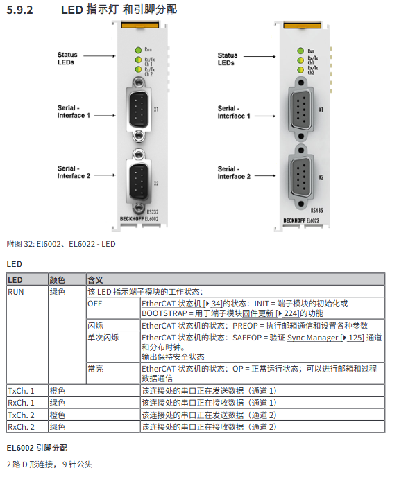
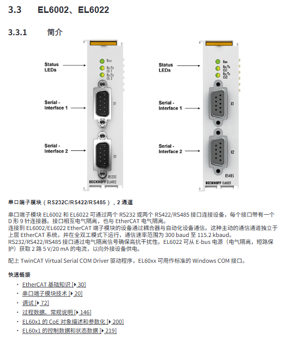
EL6002 (2-channel RS232)
Dual independent RS232, DE9 male interface, dual channel isolation, each channel has independent transmit and receive cache.
EL6022 (2-channel RS422/485)
Dual differential serial port, DE9 female port; The module can output two isolated 5V/20mA power supplies to small peripherals.
General hardware parameters
Power supply: E-Bus bus 5V power supply, current of 120~250mA for each model;
Electrical isolation: 500V isolation between EtherCAT side and serial port side;
Size: Single channel 15mm wide, double channel 26mm wide, DIN35 rail installation;
Environment: Operating at -25~+60 ℃, storage at -40~+85 ℃, humidity ≤ 95%, no condensation;
Certification: CE, cULus, UKCA, EAC, ATEX/IECEx/cFMus explosion-proof, protection IP20.
Bottom layer communication rules for serial port
Support data formats: 5/6/7/8 data bits, 1/2 stop bit, no/odd/even/mark/space check (universal formats such as 7E2, 8N1, etc.);
RS485 topology requirements: Linear daisy chain, star configuration prohibited; Connect 120 Ω terminal resistors externally at both ends of the bus;
Two types of handshakes: hardware RTS/CTS (EL600x only), software XON/XOFF, CoE parameter on/off;
Buffer mechanism: Receive overflow and loss of data, send cache to fill up and stop receiving and issuing instructions.
EtherCAT Basic Communication Principles
EtherCAT Wiring Specification
Standard CAT5 and above Ethernet cables, with a maximum length of 100m per segment, automatically recognize direct/cross connections; The maximum output of the E-Bus bus coupler is 2A. If the total current of the I/O station exceeds the limit, an EL9410 feeding module needs to be installed. TwinCAT can preview the E-Bus current.
Watchdog mechanism (SM/PDI dual watchdog)
SM watchdog: monitoring cycle process data;
PDI watchdog: monitors communication between ESC internal processors;
The timeout time can be set through the register, and the communication loss output enters a safe state, supporting the shutdown of the watchdog.
EtherCAT standard five state machine
Initialize → PreOp (email communication, no process data) → SafeOp (input refresh, output lock security value) → Op (full cycle communication) → Boot (firmware update specific).
Core of CoE Protocol
CAN over EtherCAT, Manage all parameters of the module through indexing and sub indexing; Divided into three major object intervals:
0x1000: Device read-only identity information (model, firmware, serial number);
0x4000/0x8000: Serial port baud rate, frame format, handshake, cache and other functional parameters;
0x6000/0x7000: Serial port transmission and reception process data PDO;
Modifying parameters can be stored in EEPROM for power down saving, or enable NoCoeStorage to disable write protection.
Distributed clock DC: The module supports DC synchronization, with bus level synchronization accuracy, meeting the requirements of high-speed serial port synchronous acquisition scenarios.
Installation, wiring, and explosion-proof specifications
1. ESD electrostatic protection
The operation must be anti-static, and an EL9011/9012 cover plate should be installed at the end of the terminal station to prevent static electricity from penetrating the internal serial port chip.
2. Complete specifications for explosion-proof areas (ATEX/IECEx/cFMus/UL)
The module supports the use of Zone 2 Class II explosion-proof areas, with strict restrictions on:
It needs to be installed in an IP54 or higher casing, with ambient temperatures ranging from 0 to 55 ℃ for the standard version and from 25 to 60 ℃ for the extended version;
Only plug and unplug, wire, and replace fuses in the power-off state;
The temperature resistance of the cable meets the maximum temperature requirement for the incoming line;
The official explosion-proof sustainability document can be downloaded from the official website.
3. DIN rail installation requirements
Standard 35mm TH guide rail, enhanced anti vibration scenario guide rail multi-point fixation, up to 64 12mm modules per row;
Do not stack more than two non communication modules consecutively to avoid E-Bus signal attenuation;
There is no mandatory restriction on installation orientation, but there is a reserved heat dissipation gap above and below;
Disassembly and assembly: Modular snap on structure, dual channel with front disassembly paddles, operated after power failure.
4. Wiring specifications
Spring terminal compatible with 0.08-2.5mm ² wire, stripping 8-10mm;
The serial port cable must be shielded, and the shielding layer should be grounded at a single point;
Grounding requirements: The entire guide rail shall be uniformly PE protected to eliminate EMC interference and prevent serial port garbled characters.
5. Definition of LED indicator lights
RUN light indicates EtherCAT status: off=Init/Boot, flashing=PreOp, single flash=SafeOp, constant light=OP;
Tx/Rx lights display real-time serial data transmission and reception, quickly determining whether the line is open or closed.
TwinCAT Debugging and Configuration Full Process
Step by step tutorial for TwinCAT2/TwinCAT3 environments
TwinCAT2: Independent System Manager+PLC Control dual software;
TwinCAT3: Integrated Visual Studio development;
Complete coverage: Set up target controllers, scan EtherCAT devices, create IO configurations offline/online, map PLC variables, download and run programs.
2. Key supporting tools
ESI Updating: Automatically download and update all EtherCAT device XML description files online to address module recognition deficiencies;
RT Ethernet driver: Install real-time driver on IPC network card, otherwise EtherCAT will not have real-time performance;
SCI/XTI file import and export: Batch save complete PDO and CoE configurations of serial port modules, and reuse for multiple projects;
TcVirtualComDriver: Maps the EL60xx channel to a Windows COM port, allowing the upper computer software to directly read and write the serial port. The parameter priority is higher than the CoE setting in TwinCAT.
3. Serial communication programming applications
Process data interaction logic: PDO allocation of sending and receiving cache, control word/status word management initialization, sending and receiving triggering, cache full alarm;
Three example programs: basic serial port transceiver, RS485 half duplex polling, EL6001 LIN bus master station function;
Advanced features: transmission rate optimization (automatic splicing of continuous messages), multi frame encoding switching, continuous FIFO transmission mode.
4. General debugging methods for faults
WorkingCounter、 Real time diagnosis of communication disconnection based on device status words;
Real time modification of baud rate, verification, and handshake parameters on the CoE online interface;
Support firmware online upgrade (FoE protocol), distinguishing between processor efw firmware and FPGA RBF firmware;
Can update module firmware individually/in batches, supports restoring factory default CoE parameters.
Detailed explanation of CoE object dictionary
Separate single channel EL6001/EL6021 and dual channel EL6002/EL6022 independent object tables, including:
Device read-only information (hardware/firmware version, serial number, eBIC read address 0x10E2);
Debugging diagnostic objects: cache byte count, frame error, overflow alarm;
Serial port configuration parameters (baud rate, data bits, parity, RTS/CTS, XON/XOFF, half duplex switch);
Process data PDO definition (22 byte cache for sending and receiving, supporting 16 bit wide extension to adapt to 9-bit data);
Control/status words: initialization, sending and receiving requests, cache full, frame error, communication failure flag.
Firmware, after-sales service, malfunction, scrap
Firmware upgrade: Distinguish between MCU firmware (. efw) and FPGA firmware (. rbf), download through FoE in Boot state, and the upgrade will take effect after power failure and restart; High firmware hardware is compatible with lower versions.
Equipment scrapping: It belongs to electronic waste and is classified for recycling. The internal CR2032 battery is separately recycled and processed.
Technical support: Beifu Global Hotline, official website document library, on-site/return to factory maintenance. Equipment BTN serial number is required for repair reporting.
Complete certification list: CE, FCC Class A, cULus, ATEX, IECEx, DNV classification certification, etc.