Hirschmann MACH102 Series Industrial Switch Installation Manual
Overall product architecture and model classification
MACH102 is a modular rack mounted layer 2 network management switch, consisting of a basic host and a pluggable M1 series media module, supporting flexible port expansion. The entire series comes standard with 2 Gigabit Combo uplink channels (RJ45/SFP multiplexing).
1. Basic host fixed model (non expandable media module)
MACH102-8TP-F/FR: 8 100Mbps RJ45, 2 Gigabit Combo; FR=Dual redundant AC power supply
MACH102-24TP-F/FR: 24 100Mbps RJ45, 2 Gigabit Combo; FR=redundant power supply
2 modular base models (can be equipped with up to 2 media module expansion ports)
MACH102-8TP/8TP-R: Native 8 100Mbps+2 Gigabit Combo, 2 media module slots on the body, 8 new ports added to a single module, up to 24 100Mbps expansion; R represents dual redundant AC power supply.
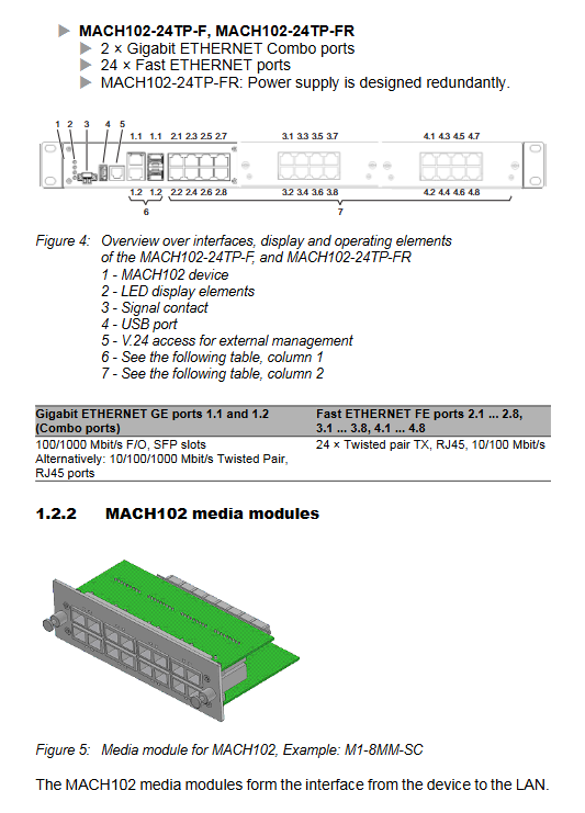
3 M1 series pluggable media module (hot swappable)
M1-8TP-RJ45: 8-port standard 10/100M RJ45
M1-8TP-RJ45 PoE: 8-port IEEE802.3af PoE, 48V phantom power supply, maximum output of 124W PoE power for the entire module
M1-8MM-SC: 8-port multimode 100Mbps DSC fiber
M1-8SM-SC: 8-port single-mode 100Mbps DSC fiber
M1-8SFP: 8 100Mbps SFP slots, freely selectable multi-mode/single-mode/long-distance optical modules
4 uplink gigabit Combo ports
The host comes with 2 sets of gigabit multiplexed Combo ports: RJ45 gigabit power+SFP gigabit slot. Inserting SFP automatically disables the corresponding RJ45.
Unified management interface for 5 aircraft bodies
V. 24 RJ11 serial port: Local CLI console, 9600 8N1, paired with ACA11 adapter
USB-A port: Supports ACA22-USB configuration USB flash drive for storing configuration, firmware upgrades, and fault logs
FAULT Passive 2-pin Relay Terminal: Remote Alarm for Whole Machine Fault
6 Core functions of the whole machine
Web/Telnet/HiVision management; DHCP/BOOTP automatic IP; HIPER Ring self-healing ring RSTP; Port automatic negotiation/automatic line sequence; Temperature monitoring; Relay fault reporting; PoE remote power supply (PoE module only).
Hardware LED indicator system
Global status light of the whole machine
P power supply: Normal model always on=normal power supply; Redundant models have dual power sources that light up yellow, single channel green, and power off when turned off
RM Ring Network Manager: Evergreen=RM enables redundant port closure; Constant yellow=redundant port activated; Flashing=ring network configuration error
Sb Standby: Always on to enable inter ring backup coupling
FAULT red light: constantly on=device malfunction (power supply/disconnection/overheating/ACA unplugged)
ACA interaction: alternating flashing of red and green=configuration read-write fault; Sync flash once=save; Sync flash 2 times=load configuration
Port indicator light
LS green light: Link status, always on, 1 flash standby, 3 flashes off, yellow light flashing represents receiving and transmitting traffic
PoE module independent yellow light: constantly on=port output PoE power supply
Complete assembly, wiring, and power on process
1. Open box verification
Check the host, installation bracket, signal terminals, and instruction manual CD, and inspect for transportation bumps.
Installation of 2 media modules (specific for modular models)
Wear an anti-static wristband and and remove the module from the conductive bag;
Remove the slot cover, install the module from left to right, and tighten the four corner screws;
Supports hot swapping, but swapping optoelectronic modules will trigger a device soft restart;
Before disassembling the PoE module, the external 48V PoE power supply must be disconnected.
Assembly of 3 SFP optical modules
Only original SFP, remove the dust cap, close the lock buckle and push it into the slot; Disassemble and open the buckle, pull it out, and promptly cover it with dust.
Choose one of the three installation methods for the 4 devices
19 inch standard rack: equipped with fixed bracket screws for locking, recommended sliding rail support for heavy loads;
Wall mounted installation: Adjust the vertical fixation of the back bracket;
Desktop flat placement: use matching anti slip bottom pad;
Reserve 10cm space on the ventilation side for all installation methods.
5 Grounding specifications
Prioritize grounding through the power circuit, supplemented by the metal bracket of the body; Connect the shielding layer of the shielded network cable to the front panel ground to avoid short circuits in the shielding layer.
6 Power wiring
Host AC terminal: 100~240V AC, – R model has two independent redundant channels. If one channel fails, it will automatically switch to the other channel. A single power supply will trigger a FAULT alarm;
PoE media module independent 3-pin terminal 48/54V SELV power supply, cable length ≤ 3m, equipped with 5A slow melting fuse.
7 FAULT alarm terminal
2-pin self-locking terminal, passive relay, maximum 1A/60VDC; Reported faults: power loss, port disconnection, device overheating, ACA unplugged, ring network failure.
8 Data cable connection
Twisted pair Cat5e up to 100m, mandatory shielding of SF/UTP in gigabit scenarios;
Fiber optic docking with the same specifications (multimode/single-mode/LH cannot be mixed);
Separate strong and weak electrical wiring to reduce coupling interference.
9. Power on self-test
After power on, the whole machine self checks for about 70 seconds, and all LEDs flash in a loop. After completion, it enters the ready state.
Basic factory default configuration
IP address: default DHCP automatic acquisition, static backup 192.168.1.1
Account: admin (password private, read-write); User (public, read-only), first login forced to change high-strength password
V. 24 serial port: 9600 baud, 8 data bits, 1 stop bit, no checksum
Port: Automatic negotiation for electrical ports, default full duplex for optical ports
Redundancy: HIPER Ring is turned off, RSTP is turned on; The port disconnection alarm is turned off by default
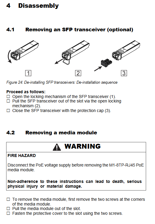
Disassembly steps
Power off, unplug all network cables, fiber optics USB、 Terminal;
Disconnect the 48V power supply before disassembling the PoE module;
Open the SFP lock and pull it out;
Loosen the four corner screws of the media module and remove it;
Remove the fixed screws from the rack/wall mounted and remove the entire machine.
Maintain standards
The whole machine has no vulnerable parts, only the FAULT relay ages with on/off, and the contacts are regularly inspected in high-frequency scenarios;
Regularly clean the dust accumulation in the ventilation opening and monitor the internal temperature of CLI/Web (about 20 ℃ higher than the environment);
Regularly download firmware updates, fix vulnerabilities, and add new features on the official website;
Equipment failure is prohibited from disassembly, and the entire machine should be returned to the factory for maintenance.
Core technical parameters
1. Mechanical dimensions and weight
Divided into 8-port base, 24 port fixed multi specification, with a total weight of 3.6~4.1kg, IP20 protection, and a metal frame body.
2 Power supply parameters
Host AC: 90~264V 50/60Hz, power consumption 12~17W;
PoE module: 45~57VDC, maximum output of 124W per module.
3 Environmental conditions
Working temperature: 0~+50 ℃, storage: -20~+85 ℃; Humidity of 10~95% without condensation; The highest altitude is 2000m, with a pollution level of 2;
Industrial grade EMC indicators such as anti-static, surge, and RF meet additional standards for railways/ships.
4 transmission distance
Copper cable: Cat5e 100m
100Mbps SFP multimode 4-5km, single-mode 25km, long-distance LH up to 140km
Gigabit SFP multimode 550m, single-mode 20km+long-distance series
5 Parts List
ACA22 USB configuration USB flash drive, V.24 debugging cable, full range of Fast/GE SFP optical modules, spare terminals, rack mounting bracket, HiVision network management software.
Supporting standards
Compatible with IEEE802.3/802.1Q/802.1w and industrial RFC protocol sets; Meets UL508, EN62368-1, FCC, GL classification and other certifications.