Basler DECS-100 Digital Excitation Control System
Chapter 1 General Information and Electrical Mechanical Specifications
1. Core four operating modes (standard AVR/FCR, VAR/PF optional)
AVR automatic voltage regulation (main mode): closed-loop stable generator terminal voltage, with adjustable soft start boost ramp, voltage regulation accuracy ± 0.25%, supporting single-phase/three-phase PT acquisition;
FCR manual excitation current mode: constant excitation current control, emergency backup for maintenance, voltage sampling and disconnection, adjustable range 0~7A DC;
VAR reactive power control (optional): grid connected constant reactive power output, absorbing/emitting reactive power -100%~+100% rated adjustable;
PF power factor control (optional): constant power factor, adjustable range of 0.6 lag to 0.6 lead.
2 core supporting functions
Soft start: adjustable boost time from 1 to 7200s to suppress startup overshoot;
V/Hz low frequency limit: inflection point 40~65Hz, slope 0~3pu, to prevent low frequency iron core saturation;
3 parallel current sharing: reactive power droop compensation adjustable from 0% to 10%, dual machine cross current differential parallel scheme;
Synchronous voltage matching (optional): automatically matches the generator and bus voltage, with two modes of maintenance/recovery;
Remote adjustment: ± 3V auxiliary DC input, ± 30% voltage constant adjustment;
Multiple sets of PID parameters: AVR/FCR, VAR/PF, OEL/UEL independent gain group, software automatically calculates PID;
Dual schemes for limiters: summation type/takeover type OEL over excitation limit, adjustable UEL under excitation limit (anti step loss phase).
3-layer hardware protection (two-level actions of alarm and shutdown)
Excitation overvoltage shutdown: 0~250Vdc threshold, fixed 10s delay, over limit cutoff of excitation;
Generator overvoltage: 100-120% rated voltage, 0-10s delay, can only alarm or shut down;
Voltage sampling loss: detect single/three-phase disconnection, switch FCR after delay or stop the machine directly.
4 Electrical input and output parameters
Working power supply: 88~250Vac 50/400Hz, maximum power consumption of 40W, supports PMG/parallel excitation two types of power supply;
Voltage acquisition: Generator and bus PT are divided into four levels: 100/120/200/240/400/480/600Vac;
Current collection: CT1A/5A two specifications, only collecting B-phase current for reactive power calculation;
Excitation output: continuous 63V/7Adc, short-term 135V/15ADC for 10s;
Communication: Backplane DB9 RS2324800 baud, local PC debugging;
Switching input: boost/buck, 52J (reactive power on/off), 52L (parallel droop), VM synchronous matching passive dry contact;
Single channel public alarm relay: 7A long-term load, fault closed output.
5 Environment and Certification
Working temperature -40~70 ℃, storage -40~85 ℃; Through UL, CE, UKCA, FCC, DNV/BV classification society, China RoHS, environmentally friendly use for 40 years.
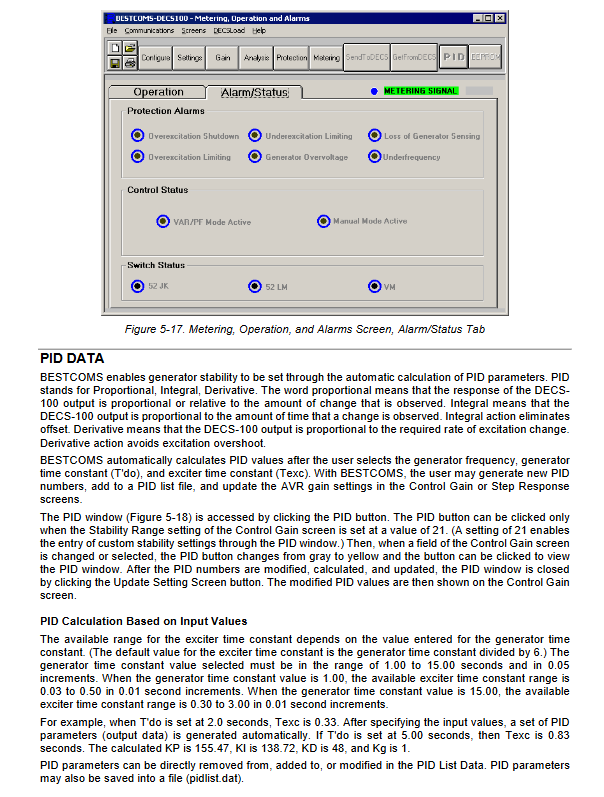
Chapter 2: Front Panel Human Machine Interface (HMI)
The whole machine has no physical buttons for adjustment, and all parameters rely on BESTCOMS software for reading and writing. The panel only has 8 status LED indicators:
Overexcitation Shutdown: excitation overvoltage shutdown;
Generator Overvoltage Alarm;
Loss of Generator Sensing: Voltage sampling loss;
Overexcitation Limitation: OEL overexcitation restriction action;
Underexcitation Limitation: UEL Underexcitation Restriction Action;
VAR/P.F. MODE ACTION: Reactive power/power factor mode activated;
MANUAL MODE ACTION: FCR manual mode activated;
Underfrequency Active: V/Hz low frequency limit input.
Backplane DB9 RS232 communication port, used for PC online debugging, reading and writing parameters, and firmware upgrades.
Chapter 3: Functional Principles of the Whole Machine
1. Hardware signal flow
PT generator/bus voltage, B-phase CT current → analog filtering ADC sampling → main control MCU operation; The power circuit rectifies and supplies power to the entire machine, and the PWM power stage outputs the excitation voltage to F+F -; Multi channel optocoupler isolation dry contact input acquisition external circuit breaker auxiliary contact.
Switching logic between two four modes
Single machine island: 52J and 52L contacts are closed, only in AVR mode;
Multi machine parallel islanding: 52L disconnected, reactive power droop put into operation;
Grid connected power grid: disconnect 52L and 52J, enable VAR/PF constant control;
Simultaneous closing: The VM contact is closed, and the voltage matching function is activated.
3. Logic of limiter operation
OEL overexcitation limit
Sum up type: Smooth transition, relying on AVR loop current limiting;
Takeover type: Directly force clamping excitation current, faster response; All with delayed alarm shutdown;
UEL under excitation limit: Based on the active reactive power curve, it prevents deep phase instability of the generator and only takes effect in grid connected mode.
4 Protection action logic
All protections can be configured separately: only alarm relay output, or alarm+cut off excitation shutdown; If voltage sampling is lost, automatic switch to manual FCR can be selected to maintain the operation of the unit and avoid shutdown.
5 Soft Start and V/Hz
Slowly increase the pressure according to the set slope when the unit starts up; If the frequency of speed decrease is lower than the inflection point, the voltage will be automatically lowered to prevent iron core saturation.
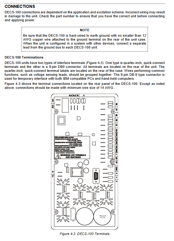
Chapter 4 Installation and Wiring Specifications
1. Mechanical installation
Installation structure of epoxy resin fully encapsulated panel, matched with self tapping screws; Metal grounding box, all shielded cables need to be grounded at one end outside the box; The installation hole size drawings are complete.
2-panel terminal partition
Power input 3/4/5: three-phase/single-phase power supply, low-voltage plant power debugging requires series current limiting resistor ICRM-7 to prevent impact;
Generator voltage E1/E2/E3: three-phase PT, single-phase short circuit E2E3;
Bus voltage B1/B3 (optional synchronous module);
CT1/CT2 B-phase current acquisition;
F+/F – excitation output connected to the excitation machine magnetic field;
A/B: ± 3V remote fine-tuning input;
6U/6D/7: Passive switch for voltage rise and fall;
52J/52K: VAR/PF input and output; 52L/52M parallel droop; VM/VMC matching during the same period;
AL1/AL2 public alarm relay output;
GND whole machine protection ground (≥ 12AWG independent copper wire);
11 DB9 RS232 communication port.
3 typical wiring schemes (5 sets of standard drawings in the manual)
PMG permanent magnet power supply+three-phase voltage acquisition;
PMG power supply+single-phase acquisition;
Generator parallel excitation power supply three-phase acquisition;
Parallel excitation single-phase acquisition;
External power supply for factory use (requires current limiting module);
Provide additional cross differential parallel CT wiring diagram for dual generators.
4 EMC/CE compliant wiring requirements
All power, sampling, and control cables use shielded twisted pair cables, with a single point grounding on the outside of the enclosure; Install a 31 specification magnetic ring at the cable conduit to suppress radio frequency interference; Separate the routing of strong and weak electricity.
5 Mandatory pre debugging requirements
Offline programming (motor not running) must remove the F+/F – excitation terminal;
Factory power>120Vac debugging, connected in series with 20 Ω/20W current limiting resistor;
The grounding of the entire machine cannot be shared with high-power equipment;
4. The withstand voltage and disassembly must be completely powered off.
Chapter 5 BESTCOMS upper software (Windows specific)
1. Software Fundamentals
Supporting debugging and configuration tools, supporting XP/Vista/7/8/10; The functions include parameter reading and writing, PID automatic calculation, real-time measurement, step response analysis, parameter file saving/batch download, firmware upgrade, and default access password decs.
2. Six core configuration interfaces
System configuration: CT/PT ratio, 50/60Hz, OEL/UEL type, synchronous function switch;
Fixed value settings: AVR voltage, FCR excitation current, VAR/PF target, droop percentage, soft start duration, V/Hz inflection point slope, synchronous speed;
Control gain PID: AVR/FCR, VAR/PF, OEL/UEL independent KP/KI/KD, built-in 20 sets of preset stable intervals, supports custom PID; Automatically generate optimal parameters by inputting the generator/excitation time constant;
Analysis interface: AVR/FCR/PF/VAR four sets of step response curves, real-time display of voltage, excitation current, reactive power, power factor, various limit alarm states, and online observation of dynamic response by increasing or decreasing fixed values;
Protection settings: overvoltage, loss of sampling, excitation overvoltage threshold and delay, OEL/UEL action parameters;
Measurement monitoring: Real time primary voltage/current/active/reactive power/power factor/frequency, excitation parameters, with a measurement accuracy of ± 0.5% for all measurements.
3 Core Software Functions
Parameter file: Save. de1 configuration file, batch copy parameters for multiple units of the same model, support text export and printing;
2. Firmware upgrade: Upload S19 firmware via RS232, and backup parameters and disconnect excitation output must be done before upgrading;
3 Password Permissions: Single password control is fully set to prevent unauthorized modifications;
4. Automatic saving of fixed values: automatically stored in EEPROM after 10 minutes of no operation;
Communication: Standard RS232 serial port. Parameters can only be read and written after communication is established. After modification, they must be saved with SEND and EEPROM to prevent loss during power failure.
Chapter 6 Maintenance and Troubleshooting
1. Preventive maintenance
Annual inspection of terminal fastening and cleaning of dust;
Idle spare parts are powered on for 30 minutes every year to extend the lifespan of electrolytic capacitors;
Components are mounted on the surface of the entire machine, and self disassembly and repair are prohibited for faults. They should be returned to the factory for processing.
2. Standardized step-by-step troubleshooting (covering typical faults)
Generator unable to generate voltage: investigate PMG/parallel excitation power supply, residual voltage ≥ 6Vac, excitation wiring, soft start parameters, OEL shutdown alarm;
Low terminal voltage: AVR constant value, droop parameter, low-frequency limit, CT/PT ratio, OEL current limit;
High terminal voltage: overvoltage setting, capacitor load droop and voltage rise, abnormal remote fine-tuning input;
Voltage oscillation swing: poor grounding, excitation grounding, inappropriate PID gain, original speed controller fault;
OEL overexcitation alarm: Unit overload, mismatched excitation winding, low current limit setting;
UEL underexcitation alarm: grid connected phase, low voltage setting, phase sequence error;
7. Reactive droop: 52L contact not disconnected, CT open circuit, pure resistance load;
8. Voltage matching failure during the same period: optional functions not activated, VM contacts, and bus PT wiring errors;
9 Sampling loss alarm: PT disconnection, single-phase acquisition E2E3 not short circuited.
Each fault is provided with hierarchical troubleshooting steps, starting from wiring → parameters → hardware step-by-step localization.