Basler BE1-60 Voltage Balance Relay
Chapter 1 Overview General Information
1. The core function positioning of BE1-60 is a dual circuit voltage difference monitoring relay, specifically designed to solve the secondary risks caused by voltage transformer PT fuse melting and PT circuit disconnection faults:
Two independent voltage acquisition circuits (Circuit1, Circuit2) compare the amplitude of three-phase voltage in real time. When the voltage difference between the two circuits exceeds the set threshold, the faulty circuit is immediately distinguished and two types of actions are output:
Alarm+orderly shutdown of the unit;
Lock overcurrent, impedance, synchronization, excitation voltage regulation and other protections to prevent PT disconnection from causing false tripping of the protection.
2. Typical application scenarios (mainly generator systems)
Power PT circuit disconnection (Circuit1 monitoring): Static excitation system no-load/full load voltage imbalance, excitation power unit overheating; BE1-60 Circuit1 output triggers an alarm+the unit shuts down normally, and the corresponding fault indicator 1 lights up;
Measurement/protection of PT circuit disconnection (Circuit2 monitoring):
Voltage constrained overcurrent relay: After PT voltage loss, the threshold of the operating current decreases, making it highly prone to misoperation;
Voltage braking overcurrent relay: When the braking voltage disappears, the protection sensitivity increases by 2.5 times, causing a fault free trip;
BE1-60 Circuit2 output disconnects overcurrent protection trip circuit, locks misoperation, and triggers emergency stop+alarm. Fault indicator 2 locates fault PT circuit.
3. Internal sampling logic (E/F type three-phase input) converts the three-phase voltage into the average three-phase voltage through a built-in Scott (T-type) transformer: \ (\ Delta V=V1- \ frac {V_{2A}+V_ {2B}+V_ {2C}} {3} \), reducing relay sensitivity;
Example: The C-phase PT of the 120V system is blown, and the circuit difference is 40V. If the setting value is ≥ 42V, it will not operate. Therefore, it is recommended to choose a smaller setting gear for the E/F three-phase sampling model.
4. Key points for setting selection: Setting should reserve a margin for normal voltage fluctuations in the system (such as a 5% fluctuation from no-load to full load of the generator, the setting value must be greater than 5%); Two channel sampling is taken from the same source voltage, and system short-circuit faults will not cause relay misoperation.
5. Model Style coding rules: Model BE1-60+segmented style code, complete definition of hardware configuration, example code D1H-A1R-C0C2F disassembly:
Sampling input type, sampling voltage range;
Main output relay contact (normally open NO/normally closed NC);
Time limit characteristics (local fixed instantaneous A1, ≤ 150ms action);
Control power specifications (24/48/125/250VDC, 120/240VAC);
Fault indicator type (built-in electronic drive/current drive, single circuit dual indicator);
Power status contacts, manual testing buttons;
Number and type of auxiliary output contacts;
Shell installation method (semi embedded S1 shell).
6. Core electrical specifications (1) Voltage sampling
Standard sampling: three-phase star shaped 208V line voltage, three-phase delta 120V line voltage, single-phase 120V;
Normal monitoring range: rated voltage 60%~125%; Continuous tolerance to 160% Un;
Action setting: 5%~50% rated voltage, step size 5%; Accuracy of 1V or 5% setting value (whichever is greater);
Return value: ≥ 90% of action value; The fault difference is more than 3 times the set value, and the action time is ≤ 150ms.
(2) Control power supply (Class 5 specifications)
Table Power Supply Type Rated Voltage Operating Range Power Consumption Special Instructions R Low Voltage 24VDC 12~32VDC 1.2W requires 14VDC for startup, and can be as low as 12VO/S Medium Voltage 48/125VDC 24~150VDC 1.1~1.4W DC General P AC 120VAC 90~132VAC 11.2VA AC Power Supply T High Voltage 250VDC/240VAC 62~280VDC/90~270VAC 1.6~18.8VA High Voltage Cabinet Suitable for power supply polarity free, isolated low load design.
(3) There are two options for the fault indicator Target:
Built in driver type: can light up without tripping the circuit current;
Current driven type: The trip circuit can only be triggered when it is ≥ 200mA, with a short-term withstand of 30A/0.2s and a long-term withstand of 7A;
Before 2007, it was a mechanical disk latch, but now it has a unified electronic latch LED. When the power is turned off and restored to the latch state, it needs to be manually reset.
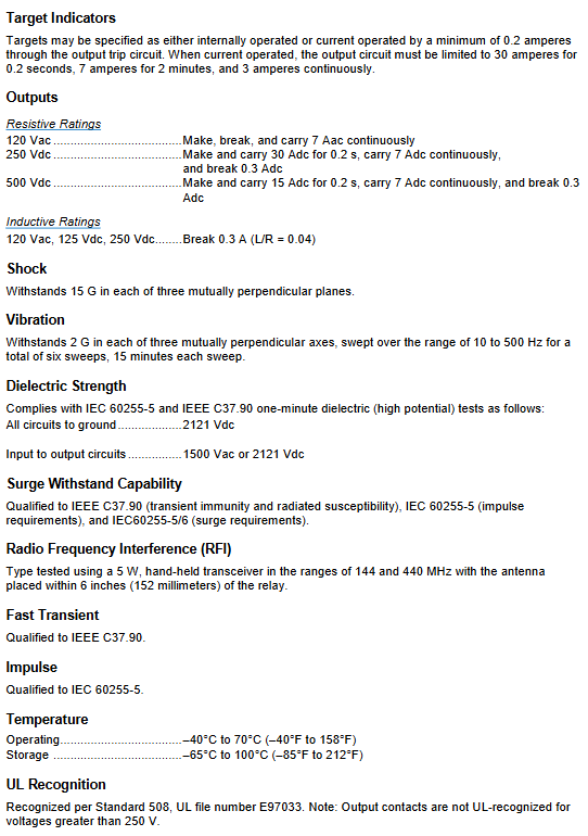
(4) Output contact capacity (resistive load)
120VAC: Continuous on-off load of 7A;
250/500VDC: Short term connection of 15-30A (0.2s), long-term 7A, disconnection of only 0.3A;
The inductive load is uniformly disconnected at 0.3A (L/R=0.04).
(5) Environmental and reliability testing
Impact: Three axis 15G without damage; Vibration: 2G, 10~500Hz sweep frequency;
Voltage resistance: The whole machine is grounded at 2121VDC, with 1500VAC between input and output;
Electromagnetic compatibility: meets IEEE C37.90, IEC60255-5 surge and RF anti-interference standards;
Certification: UL508 certification, no UL certification for contact voltage>250V;
Physical parameters: Maximum weight 6.46kg, unified S1 shell.
Chapter 2 Panel Controls and Indicators
All components are integrated into the front panel, with a total of 5 types of components:
Differential Limit Switch
10 adjustable levels (A~K, skip I), 5%~50% rated voltage, step size 5%, set the maximum allowable voltage difference between two PT channels; The panel scale corresponds to the percentage of each gear.
B Fault lock indicator light (optional)
Two independent red LEDs, Circuit 1/Circuit 2 fault corresponding lights up, electronic latch, manual reset required.
C output test button (optional)
Concealed openings on the panel, press the insulated thin rod, manually trigger two main output relays, and verify the secondary circuit wiring.
D indicator reset switch
Clear the lock fault light and reset the alarm signal.
E power running LED
The relay stays on when the power supply is normal and goes off when it loses power.

Chapter 3 Functional Description
1. Signal processing flowchart: Two PT three-phase voltages → Built in step-down transformer → Full wave rectification+integration circuit (converted into DC amplitude signal) → Differential amplifier (compares the two in-phase voltages, calculates the difference, and determines which voltage is lower) → Set reference comparator → Fault output logic → Drive main relay/auxiliary output/fault indicator light.
2. Core module description
Step down transformer: isolate the PT circuit once and reduce the high voltage to the weak current processing section;
Rectification integration: AC voltage is converted to DC, and the DC level represents the effective value of the circuit voltage;
Differential amplifier: phase wise comparison of Circuit 1 and Circuit 2 in-phase voltages, outputting a differential signal;
Setting reference circuit: The dial switch generates a reference DC voltage, representing the maximum allowable voltage difference;
Comparator: if the pressure difference is greater than the set value, output a trip command; Two fault signals are used as OR logic to drive the corresponding circuit output;
Return delay of 0.75s: After the fault disappears and the voltage difference drops below the set value, the output relay will reset after a delay of 0.75s to avoid frequent voltage fluctuations and shaking.
3. Classification of output circuits
Main trip output (two independent circuits)
Circuit 1 and Circuit 2 each have a set of main relays, with optional NO/NC contacts: the circuit with low voltage when disconnected corresponds to the relay action, used for shutdown and lockout protection.
Auxiliary output (optional)
Two independent auxiliary contacts, NO/NC/SPDT optional; Under special configuration, Circuit2 auxiliary contacts are reused as power status monitoring contacts; Any fault in any of the auxiliary contacts of Circuit 1 will activate.
Power status contacts (optional)
Regularly open during normal power supply; When the relay loses power/internal power failure occurs, it closes to monitor abnormal power supply of the device.
4. Fault indicator driving logic
Built in driver: The output action directly lights up the LED without current requirements;
Current driven: The output contact must be closed and the tripping circuit must have a current of ≥ 200mA to light up;
After a power outage, the light goes out, and when power is restored, the fault state is automatically locked before restoration.
Chapter 4 Installation
1. Receipt, storage, and maintenance
Upon arrival, verify the model and appearance, and immediately report any damages during transportation to the carrier and sales team;
Not installed temporarily: stored in the original box for moisture and dust prevention; Backup equipment can be powered on for 30 minutes every year to extend the lifespan of electrolytic capacitors;
Maintenance: No preventive maintenance, only regular functional verification; Contact the manufacturer’s after-sales service directly for any malfunctions.
2. Install safety regulations
The current driven indicator must ensure that the tripping circuit current is ≥ 200mA;
Before the withstand voltage insulation test, unplug the terminal plug and extract the relay body, otherwise the protection will be lost;
Confirm the stability of the system operating conditions before dismantling the relay to prevent equipment accidents caused by PT disconnection protection failure;
Grounding: The cabinet grounding terminal uses ≥ 12AWG copper wire for independent grounding, and multiple devices are grounded separately;
EMI suppression (Rev G added): When the contact drives the external coil, the coil is connected in parallel with a reverse freewheeling diode to absorb surges;
Solid state without mechanical structure, no mandatory vertical installation requirements, and can be installed at any angle.
3. Shell and opening size
Unified S1 standard housing, providing two types of installation drawings (semi flush, protruding projection), with dual inch/millimeter markings: panel openings, backplane terminal layout, side view thickness, fixing screw specifications, and outer shell dimensions.
4. Wiring specifications
Conventional wiring wires should not be less than 14AWG, and the model should be checked before wiring to prevent the relay from burning out;
Sampling input: distinguish between A/B/C/D/E/F six types of sampling wiring diagrams, and adapt to single-phase, star three-phase, and delta three-phase PT secondary circuits;
Typical wiring diagram for output control circuit: main trip, auxiliary contacts, power status, fault indicator, generator excitation, overcurrent protection interlock.
Chapter 5 Testing
Complete machine function verification process (taking 120V standard sampling as an example)
Set the dial to the minimum A (5%), apply 120Vac to both inputs, reset the fault light, and maintain normal output;
Slowly increase the phase A voltage of Circuit 1 to 125~127Vac, if the voltage difference exceeds the limit, Circuit 2 output will activate; Restore 120V, automatically reset within 0.75s;
Set the dial to the maximum K (50%), reduce Circuit 1 A phase to 57-63Vac, and Circuit 1 output action; Restore the rated voltage and reset in 0.75s;
B/C/D three-phase sampling model, repeat the above steps to verify B and C phases;
Models with manual testing buttons, press the button to confirm reliable operation of the two output contacts.