
Basler UFOV250A/UFOV260A Low Frequency Overvoltage Module
Product Description and Technical Specifications
(1) Two core functional principles
1. Low frequency underfrequency protection (V/Hz function)
Action threshold: When the frequency is lower than the rated value by 4-7 Hz, the limit is applied; The threshold for the old and outdated modules is 10Hz, and the new version has been optimized.
Adjustment logic: The lower the frequency, the proportionally lower the generator voltage, and the voltage will automatically rise again after the speed returns to the rated level; The voltage drop rate is slightly faster than the frequency drop rate.
Priority of excitation: When the unit is first pressurized, the AVR excitation relay has a higher priority than this module and will not interfere with residual voltage excitation; Long term low-speed operation requires ensuring the normal power supply of the excitation circuit.
Characteristic curve: There is a tolerance band in the voltage frequency range, which is affected by temperature and component tolerances.
2. Overvoltage protection
Action range: The rated voltage within the setting range is 125%~150%, and the factory default is 130% Un;
Execution logic: After detecting sustained overvoltage, the supporting circuit breaker is tripped, the AVR input power is cut off, and the excitation is completely shut down; After detachment, it must be manually reset to restore pressure regulation;
Fault diagnosis: Frequent tripping due to load shedding indicates that the setting value is too low and needs to be adjusted appropriately to avoid transient voltage spikes; After tripping, the root cause of overvoltage must be investigated before resetting.
Circuit breaker selection: single pole (part 05390)/double pole (part 05391), both supporting 480Vac, 50A contact capacity; SR-F/SR-H models must use bipolar circuit breakers.
(2) Electrical specifications
Single phase voltage input: supports multiple levels of 120/208/240/416/480/600Vac, 50Hz (250A)/60Hz (260A); Built in multi tap sampling transformer, factory default 120V gear.
Underfrequency threshold: rated frequency is lowered by 4-7 Hz; overvoltage setting is 125%~150% Un.
(3) Mechanical and environmental parameters
Seismic and impact resistance: multi frequency vibration tolerance, three-axis 15G impact;
Working environment: -55 ℃~+70 ℃;
Installation method: Cabinet backboard installation, placement at will does not affect performance;
Weight: Net weight 4.5kg, packaging 5.5kg.
Detailed explanation of working principle
1. Underfrequency circuit
When the unit is running at low speed, the excitation output will automatically decrease, and the voltage will linearly decay with frequency; During the start-up phase, the excitation relay shields this module to ensure voltage building; Long term low-speed operating conditions require confirmation of continuous power supply to the excitation circuit.
2. Overvoltage circuit
Continuous overvoltage triggers the circuit breaker, disconnects the AVR power supply circuit, and forcibly cuts off the excitation; After tripping, manual reset is required, and the root cause of the fault needs to be investigated before putting it back into operation; Match single/double pole circuit breakers according to AVR models.
Installation, wiring, and configuration
1. Mechanical installation
Provide dimensional drawings of the module body and single/double circuit breakers, with fixed backboards and no installation angle restrictions.
2. Input voltage gear adjustment
Internal sampling transformer with multiple voltage taps, default 120Vac; When the unit voltage is not 120V, manually change the wiring to the corresponding gear; If the unit voltage exceeds 600Vac, an external PT voltage transformer must be connected.
3. Key wiring specifications
Universal terminals: 1 and 2 are power sampling inputs; C. D outputs a trip signal to the overvoltage circuit breaker; N is the AVR linkage terminal;
Multiple sets of standard wiring diagrams: compatible with the full range of AVRs such as SR4/8A, SR32A, SR-F/SR-H/SR63H;
Paired with SBO excitation support system: UFOV sampling cannot be connected to AVR power supply, it must be connected to SBO circuit;
There are two connection methods for matching EMI filtering modules: EMI248/208 requires connecting the UFOV terminal N to the filtering F+, and the circuit must not be grounded;
Differences between the old and new versions of terminals: The old UFOV terminal numbers are 3/4/6, while the new version has been changed to P/C/D/N. The wiring points have been changed and the drawings cannot be mixed.
Wiring precautions
If AVR terminal A is used for the excitation battery circuit, an additional isolation circuit breaker needs to be installed to protect the battery circuit.
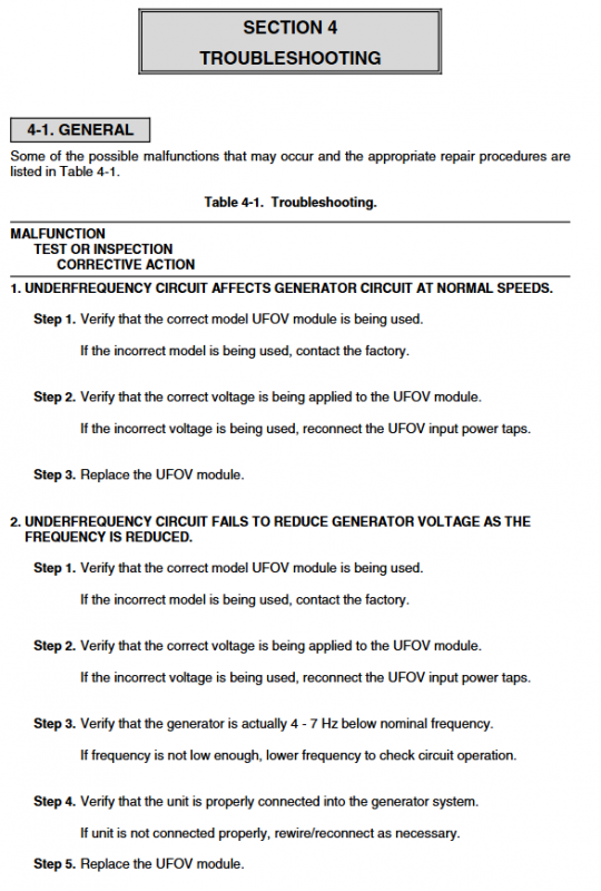
Troubleshooting (4 typical types of faults)
Fault 1: Underfrequency function misoperation at rated speed
Check if the 50/60Hz model matches;
Check if the input voltage tap connection of the module is correct;
The module hardware is damaged, replace the entire machine.
Fault 2: No voltage reduction restriction effect when the frequency drops
Check the model and input voltage level;
Is the measured frequency lower than the rated 4-7 Hz;
Thoroughly verify the system wiring;
Module malfunction replacement.
Fault 3: The circuit breaker does not trip when overvoltage occurs
Check for virtual connections and broken wires in the circuit;
Reset the overvoltage action value;
The circuit breaker coil is damaged, replace the switch;
Replace the module body due to malfunction.
Spare parts
List the original part numbers of core replaceable component boards, inductors, and sampling transformers, and indicate the module model for repair procurement.
UFOV260A motherboard: 9 1051 00 100
UFOV250A motherboard: 9 1051 00 101
Matching choke coil, sampling transformer and other accessory numbers.