Basler CBS310/CBS320 current strong excitation system
Overall description and specifications
1.1 System Composition and Working Logic The CBS system consists of two parts: a current enhancement module and a dedicated current transformer CT.
Trigger logic: Collect APR regulator CB+and CB – contact signals as excitation triggers;
Power supply source: Generator A and C two-phase outgoing CT, with CT output as the sole excitation power source under short-circuit conditions;
Suitable units: three-phase three wire, three-phase four wire synchronous generators;
Three phase three wire: supports continuous excitation due to phase to phase short circuit;
Three phase four wire: can maintain A/C relative ground short-circuit excitation, B phase ground can rely on the voltage of the other two phases to maintain a certain excitation output;
Automatic adaptation: The system automatically matches the strong excitation output threshold based on the rated voltage of the generator and dynamically adjusts it according to the terminal voltage.
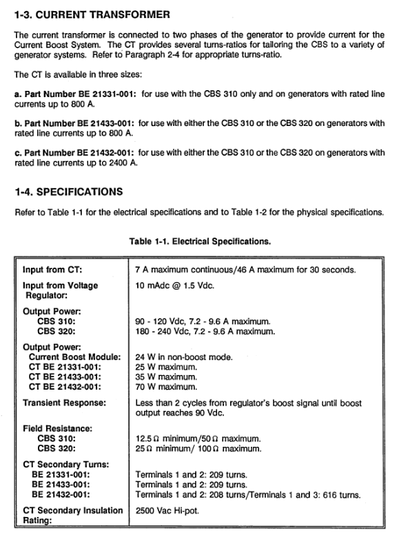
1.2 Three specifications of CT matching (selected according to the rated current of the generator)
CT part number/compatible model/upper limit of rated line current of generator
BE21331-001/Only CBS310/800A
BE21433-001/CBS310/CBS320/800A
BE21432-001/CBS310/CBS3202/400A
CT secondary side withstand voltage of 2500Vac, with multiple secondary side taps (standard 209 turns), and the transformation ratio can be adjusted by changing the number of through turns once. 1.3 Electrical Core
Module input trigger: 10mA @ 1.5Vdc (from APR CB+/CB -);
The maximum output power of CBS310 is 35W, and the maximum output of CBS320 is 70W;
Adaptive impedance of excitation winding: minimum 25 Ω, maximum 100 Ω;
The CT secondary standard winding has 209 turns and supports multiple gear ratio combinations.
1.4 Environmental and Physical Parameters
Storage temperature: -65 ℃~+85 ℃; Working temperature: -40 ℃~+60 ℃;
Impact resistance: three-axis 15G tolerance; Anti vibration, fully encapsulated moisture-proof condensation;
Weight: The net weight of the current enhancement module is 2.84kg; each CT model is labeled with net weight and packaging weight;
Mechanical drawings provide modules, three types of CT openings, window dimensions, and installation references.
Installation, ratio calculation, wiring scheme
2.1 Mechanical installation requirements
CBS module: standard cabinet backplate installation;
CT installation: The cables of generator A and C are passed in reverse through the CT window (with opposite directions); Busbars/cables need sufficient insulation and mechanical support for short-circuit conditions;
The size of the CT window should match the total cross-sectional area of the cable and be checked during selection.
2.2 The complete set of standard wiring diagram manual provides a complete interconnection diagram for multiple working conditions:
CBS standard wiring for 208~240V generators;
416-480V generator CBS standard wiring;
3 CBS with isolation transformer wiring;
4. CBS and MVC manual voltage regulating device are connected together;
5. Dual CT scans are used to collect wiring schemes for phases A and C respectively;
Wiring diagram for offline testing of 6 racks.
2.3 CT Transformation Ratio Complete Calculation Process (Core Chapter) Objective: To control the excitation current during a short circuit and limit the short-circuit current to not exceed the unit’s tolerance value through matching the number of through turns and CT secondary tap. Basic calculation formula
Short circuit excitation current: \ (I2 {Field}=E/R \)
2 CT secondary target current: \ (I2 {CTSEC}=I2 {Field} × 1.25 \)
3 ampere turns calculation: \ (P_ {AT}=209 × I2 {CTSEC} \)
4 turns per phase: \ (N_ {PRI}=P_ {AT}/(1.73 × I2 {short circuit}) \), the result is rounded up
5. Long term ampere turn verification: Continuous rated current x number of turns<800 ampere turns, exceeding the upper limit requires contacting the manufacturer
Two selection methods
Quick table lookup method (Table 2-1 three-phase/Table 2-2 single-phase): directly match the number of turns based on short-circuit current and target excitation current: 209 turns secondary side transformation ratio;
2. Precision calculation method: suitable for high-precision excitation setting scenarios, step-by-step calculation of ampere turns, turns, and long-term current carrying capacity.
If the current limiting solution calculates that the short-circuit current exceeds the standard, a current limiting resistor should be connected in series in the excitation circuit:
\(R_{S}=E/I_ {2}-R_ {f}\)
Rs is a series resistor, which should not be too large to avoid insufficient strong excitation under normal operating conditions.
2.4 Optional Delay Relay (Optional Extension) 1 Function: Strong excitation timeout over excitation shutdown, manual mode locking CBS output;
2 parameter requirements: maximum delay of 30s, coil voltage adaptation to 208/240/277Vac; Contact 240Vac, long-term 7A, short-term 45A;
3 Logic: Strong excitation continues beyond the time limit, cutting off the excitation circuit to protect the rotor.
Operation verification and bench testing
3.1 On site installation verification steps: 1. Check the direction of the CT core, the number of turns in the variable ratio, and all wiring in the shutdown state;
2. Start the unit with no load, first verify the basic voltage regulation function of the APR regulator;
Connect a DC voltmeter to the CBS output terminal to simulate fault conditions and detect strong excitation output;
4. Measure the CT secondary current and verify that it is consistent with the theoretical value using the transformation ratio formula;
Complete verification of strong excitation switching under 5 load and short-circuit simulation conditions.
3.2 Offline bench testing process: 120Vac AC power supply, 60-100W bulb simulated excitation load;
After connecting the wires, turn on the power and observe the status of the BOOST indicator light. After disconnecting the power, the high-voltage terminal should wait for the indicator light to completely turn off before disconnecting to prevent electric shock.
3. Overview of Working Principle: CBS is automatically controlled by APR regulator throughout the process, without manual operation; The system detects a short circuit in the generator, and the CT induced power is directly added to the excitation winding, providing top value strong excitation to increase the system’s short-circuit capacity. After the fault disappears, the strong excitation is automatically exited.