ADLINK PCI/MPC/PXI-8164 Three in One Motion Control Card
Product Overview and Core Differentiation of Three Models
1. Unified universal core performance (three completely identical)
1.4-Axis independent motion channel, maximum pulse output 6.55MHz, supports OUT/DIR, CW/CCW, AB phase three pulse output modes
2. Speed curve: dual modes of trapezoidal and pure S-curve, shock absorption and noise reduction, and reduction of mechanical impact
3. Interpolation ability: Continuous interpolation of any 2-axis arc and 2-4 axis straight line, supporting continuous contour machining without pause
4. Hardware functions: real-time online speed/position adjustment, 13 types of zero return logic, hardware backlash compensation, vibration suppression, software positive and negative limit
5. Encoder: 28 bit bidirectional counter per axis, supporting 1/2/4 times frequency A/B/Z phase feedback
6. High speed hardware: 2-channel CMP output for position comparison (triggered by visual photography), 2-channel LTC input for position locking (positioning capture), built-in 4K FIFO cache
7. Isolation: All on-site IO 2500Vrms optoelectronic isolation, industrial anti-interference
8. Synchronization: Multi card daisy chain global synchronization start stop; Rich hardware interrupt sources (limit, alarm, zero return, comparison trigger, etc.)
9. Handwheel MPG input, external handheld unit manual point control
10. Software support: Windows visual debugging tool Motion Creator, DOS/Windows/Linux C/C++/VB development library
2. Differences in bus and hardware among the three models
|Model | Bus specifications | Structural dimensions | Exclusive IO features | Maximum number of cards in the system|
|PCI-8164 | Standard 32-bit PCI card | Half length PCI | 6-way universal TTL output, independent STA/STP synchronous terminal, external 24V power supply interface | 12 cards (48 axes)|
|MPC-8164 | PC104 Stacked Bus | PC104 Small Board | 8DI+8-way Isolation Universal DIO, Dialing Set Base Address/IRQ | 4 sheets (16 axes)|
|PXI-8164 | PXI Rev2.0 3U European Card | 3U PXI Modular | PXI Dedicated Trigger Bus, 4-way Isolation DIO, Card Number Dialing 0-11 | 12 Cards (48 Axes)|
3. Applicable scenarios
-PCI-8164: Standard industrial control desktop computer, vertical control cabinet
-MPC-8164: Embedded PC104 Single Board Computer, Compact Embedded Device
-PXI-8164: PXI test and measurement chassis, multi card high-precision synchronous testing platform
Hardware specifications and electrical parameters
1. Clock: 19.66MHz internal reference crystal oscillator
2. Pulse frequency range: 0.1PPS~6.55MHz, three-level magnification adjustable
3. Counter range: ± 134217728 (28 bits)
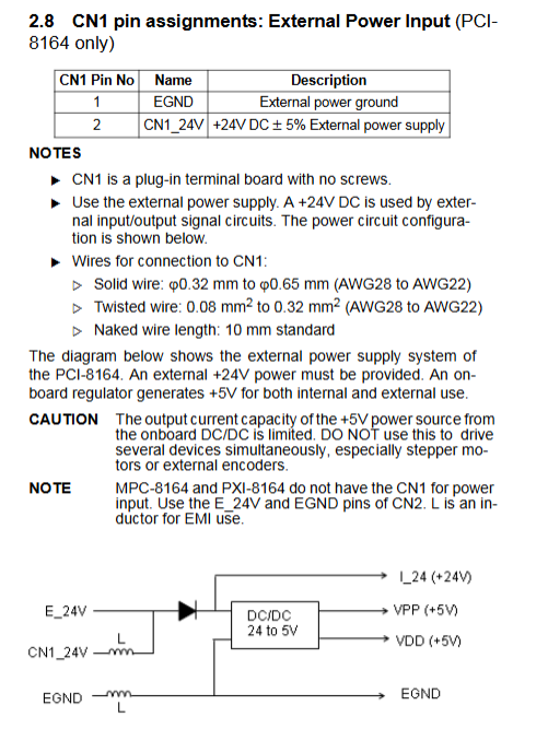
4. Power supply: Host slot+5V (maximum 900mA); External 24V isolated power supply (maximum 500mA), onboard DC-DC output 5V peripheral power supply
5. Environment: Working at 0-50 ℃, storage at -20~80 ℃, humidity at 5%~85%, no condensation
6. Output driver: Pulse differential (default)/Open collector jumper switch, Open collector current ≤ 20mA
7. Servo IO driver: SVON, ERC output voltage withstand 35V/50mA; ALM/INP/RDY input adapted to 5V open set servo signal
Hardware layout, connectors, and jumper dialing of the entire machine
1. PCI-8164 onboard interface
-CN1: External 24V power terminal
-CN2: 100pin SCSI main signal port (4-axis all pulse, encoder, limit, servo IO, CMP/LTC)
-CN3: 4-axis handwheel PA/PB pulse input
-CN4: Multi card synchronous STA/STP start stop terminal
-CN5: 6-channel universal TTL digital output
-J1~J8: Pulse differential/open set jumper for each axis
-S1: Limit switch normally open/normally closed logic dip code
2. MPC-8164 onboard interface
-CN2: 100pin main motion signal SCSI port
-CN3: 8 isolated DI+8 isolated DO universal terminal
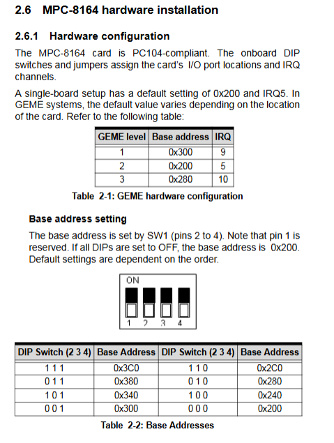
-SW: I/O Base Address DIP Dialing
-JP1: IRQ interrupt selection jumper
3. PXI-8164 onboard interface
-CN2: 100pin main motion SCSI port
-J3:4 channel isolation DI/DO
-J4:4 axis handwheel pulse input
-S1: Limit logic switch; S2:0~11 card number dialing code
-Front PXI trigger bus, hot plug status LED
4. General CN2 main 100 pin terminal signal grouping (shared across the entire series)
Each axis has an independent complete set of signals, and the 4 axes are arranged uniformly:
1. Pulse output: OUT ±, DIR ± (differential pulse)
2. Encoder feedback: EA+/EB+/EZ+(A/B/Z differential phase)
3. Mechanical switches: PEL positive hard limit, MEL negative hard limit, ORG origin, SD deceleration PCS signal
4. Servo specific IO: SV servo enable output, ALM fault input, INP in place input, ERC deviation reset output
5. High speed trigger: CMP position comparison output (axis 1/2), LTC position latch input (axis 3/4)
6. Onboard isolation 5V, external 24V ground EGND
Hardware installation and driver installation process
1. Pre installation specifications
1. Anti static operation, grip the edge of the board and prohibit touching the chip
2. PCI/PXI plug and play, BIOS automatically allocates I/O and IRQ; MPC-8164 requires manual dialing of base address and interrupts
Pre configured differential/open set with 3 pulse output jumpers, matched with on-site switch types for limit dialing
2. Installation steps for Class III boards
PCI-8164: Turn off the power and insert it into the 32-bit PCI slot for fixation. Connect the 24V power supply → CN2 servo cable → handwheel/synchronization terminal in sequence
2. MPC-8164: PC104 stacked installation, set non conflicting addresses and interrupts through SW1/JP1, and then connect external IO
3. PXI-8164: Insert the PXI chassis slot, lock the buckle, and use the chassis backplane to synchronize the clock uniformly
3. Driver installation
1. Windows: Insert the matching All in One CD, select the motion control driver installation, restart to take effect
2. DOS: Loading low-level libraries from the DOS directory on a CD
3. Linux: Supporting kernel drivers and compilation examples
4. MPC Additional Tool: Add registration program to match dialing address
All IO signal electrical wiring specifications
The manual provides a complete schematic of each signal, selection of external resistors, and cable matching scheme:
1. Pulse output: Differential long line anti-interference priority; Short distance separation requires a 470 Ω current limiting resistor in series, with a current not exceeding 20mA
2. Encoder wiring: Differential encoder directly connected; Open set encoder 5V without resistance, 12V string 1.8k, 24V string 4.3k resistance
3. Limit/origin SD switch: 24V contact input, onboard optoelectronic isolation, supports normally open/normally closed software/DIP switching
4. Servo INP/ALM input: compatible with driver open set output, onboard 470 Ω pull-up circuit
5. ERC/SVON output: maximum 35V 50mA, used for clearing servo position deviation and enabling servo power on
6. CMP trigger output: When the set pulse is reached, TTL pulses are automatically output to dock with the camera and laser
7. LTC latch: External sensor triggers instant capture of encoder precise coordinates
8. Multi card synchronous CN4 daisy chain parallel connection, all cards start/stop motion synchronously
Working principle of motion control core
1. Pulse output in three modes
1. OUT/DIR single pulse (mainstream in the industry): pulse distance, level control direction
2. CW/CCW dual pulse: Two pulses move positively and negatively respectively
3. AB orthogonal phase pulse: analog encoder output, compatible with special drivers
2. Two major types of speed curves
1. Trapezoidal Curve: Constant Acceleration and Deceleration, Simple Point Location Scene
2. S-curve: Smooth transition at the beginning and end of acceleration and deceleration, divided into linear segments and S-buffer segments. Linear pure S-mode can be turned off to reduce mechanical vibration
3. All sports modes
1. Constant speed motion: tv/move trapezoid, sv/move S curve, supports dynamic variable speed during operation
2. Uniaxial point position: absolute ta \ _cove, relative tr \ _cove; S-curve sa_ move/sr \ _ move
3. Multi axis interpolation
-2-axis straight line, 2-axis arc (independent interpolation of XY/ZU groups)
-3/4-axis spatial linear interpolation
-Continuous contour interpolation, multi-level FIFO cache, seamless connection of multiple trajectory segments
4. Zero return to origin: 13 search logics (limit reverse zero finding, ORG+Z phase dual positioning, multi-stage deceleration, etc.)
5. Handwheel Follow: Real time mapping of motor motion with external PA/PB pulses, adjustable magnification software
6. Synchronous motion: triggered by multi card hardware synchronization, simultaneously starting and stopping all axes
4. Featured hardware functions
1. Online modification of position/speed: Real time update of target coordinates and maximum speed during motion without stopping the machine
2. Hardware backlash compensation: Reverse motion automatically superimposes compensation pulses to eliminate screw clearance
3. Hardware location comparison/latch: No CPU polling required, ASIC hardware captures coordinates and outputs triggers
4. Rich interrupt system: Limit, alarm, zeroing completion, comparison trigger, encoder exception can all register interrupts
Motion Creator Visual Debugging Software
Windows programming free debugging tool, used for installation verification, parameter pre tuning, and troubleshooting:
1. Automatically scan all 8164 cards in the machine, displaying card numbers and hardware addresses
2. Axis parameter configuration: pulse mode, encoder multiplier, limit logic, zeroing parameter, speed curve
3. Single axis debugging panel: Real time display of command position, encoder actual position, deviation, IO indicator light
4. Interpolation simulation interface: 2D drawing of straight/circular trajectory, preview of machining path
5. Import and export parameter configuration files, which can be directly loaded in the user program
6. IO monitoring, interrupt simulation, and handwheel simulation functions
C/C++/VB complete development function library
Complete API categorized by function, accompanied by error codes, parameter descriptions, and example codes:
1. Initialization class: card scanning, hardware reset, loading configuration
2. Pulse encoder configuration: output mode, AB multiplier, motion ratio (gear compensation)
3. Single axis motion: constant speed, trapezoidal/S-shaped point position, dynamic variable speed, emergency stop/slow stop
4. Multi axis interpolation: a complete set of functions for straight lines, arcs, and continuous contours
5. Return to zero, handwheel control function
6. Servo IO read-write: SVON output, read ALM/INP/RDY status
7. Position comparison C, position latch LTC parameter settings
8. Interrupt registration, wait for interruption, and read interruption status
9. Backgap compensation, software limit, multi card synchronous control
10. MPC/PXI exclusive universal DIO read-write function
Standard wiring case of servo drive
Supporting DIN terminal board selection (DIN-814M Mitsubishi, DIN-814P Panasonic, DIN-814Y Yaskawa, etc.), providing a complete one-to-one pin comparison table:
1. Complete wiring diagram for pulse and encoder
2. Limit, origin, servo alarm/in place standard wiring
3. Matching scheme for ERC bias reset circuit
4. Wiring specifications for 24V external power supply