Installation, operation, maintenance, and spare parts of Bonfiglioli HF series reducers
Original IOM manual for Bangfeili HF series industrial gearboxes (HF40, HF70, HF125), accompanied by exploded view and complete spare parts list; This series is mainly suitable for motor drive and can be used for industrial working conditions such as lifting and hoisting. This version is a regular non ATEX explosion-proof model and cannot be directly used in explosive hazardous environments.
Security Information
Operators must receive specialized training and be equipped with personal protective equipment; Maintenance and repair are only available to professional technicians.
Equipment body noise<85dB (A) @ 1m; The overall noise of the gearbox was tested by the manufacturer of the gearbox in accordance with the Machinery Directive 2006/42/EC.
The gearbox without a backstop can rotate in both directions; There is a risk of losing control and falling due to power outage when lifting class loads, and a power-off brake must be configured.
In high-altitude installation scenarios, the complete machine factory must provide a maintenance platform for maintenance personnel to operate.
Important prohibitions:
Do not use high-pressure water guns to flush the box body;
It is strictly prohibited to use the gearbox body as a welding grounding electrode, as it may damage the gears and bearings;
Before maintenance work, the power must be cut off and locked with a tag to prevent accidental start-up;
During operation, the surface of the shell may become hot, posing a risk of burns; Protective gear must be worn for hot oil discharge;
Equipped with a pressure relief valve vent plug, wait for the entire machine to cool down before disassembly.
Special high-risk working conditions (suspension installation, motor fully supported by reducer, downward arrangement of expansion disk output shaft) require the addition of safety chains and restraint protection devices.
The manufacturer of the complete machine needs to incorporate the key points of this manual into the overall operation manual.
Technical information
3.1 Identification of nameplates
The nameplate includes: model TYPE, product code CODE, manufacturing year and month, installation location MOUNT.POS., reduction ratio, manufacturer; The nameplate must be kept clear and readable; Repair requests and orders for spare parts must reference nameplate information.
3.2 Equipment Description
HF series gearboxes are used for mechanical equipment integration and are driven by motors; Suitable for industries such as machinery, chemical, and agriculture, with a variety of accessories and configurations.
This manual does not have an explosion-proof design and is not allowed to be directly used in potentially explosive environments.
3.3 Compliance
Meet basic health and safety requirements; The supporting motor meets the low voltage command and EMC electromagnetic compatibility command.
3.4 Usage Restrictions
Prohibited for use in environments with strong corrosion/abrasion, smoke and dust; Prohibit direct contact with bulk food materials; Without ATEX explosion-proof certification, it shall not be used in explosive hazardous areas.
3.5 Temperature limit
Continuous maximum surface temperature of the shell:+100 ℃;
Maximum continuous oil temperature of lubricating oil:+95 ℃;
It is not recommended to operate continuously for a long time within the oil temperature range of 80-95 ℃; It is recommended to perform a speed ramp soft start when starting at full load.
Handling, transportation, and storage
4.1 Packaging
Standard cardboard tray packaging is suitable for land transportation and is not rainproof; Customized wooden boxes are required for sea freight/humid environments; Indoor storage, humidity ≤ 80%, unopened storage for up to 2 years; Verify the order upon receipt and inspect for any visual damages.
4.2 Handling and Lifting
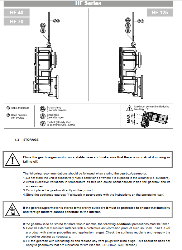
Lifting equipment must be used for weights greater than 15 kg; It is prohibited to use motor lifting rings to lift the entire gear motor;
The maximum allowable swing for lifting is ± 15 °; If the swing exceeds the tolerance, it must be re lifted;
The center of gravity will change with the flange, accessories, and motor, and it is necessary to increase the lifting points;
Lift slowly, check stability before moving.
4.3 Storage Requirements
Prohibit outdoor storage; The equipment should be elevated and not directly in contact with the ground; Avoid drastic temperature changes and prevent internal condensation.
Storage for more than 6 months: Apply rust inhibitor to exposed machined surfaces; Add lubricating oil to the box and replace the ventilation plug with a closed plug; Excluding lifetime lubrication models.
Long Term Stock option for long-term inventory
VpCI gas-phase rust proof bag packaging; The packaging box is labeled as “only open before installation”;
Storage conditions -10 ℃~+40 ℃, dry and away from light, maximum storage for 2 years; Upon expiration, it must be sent to Bangfeili Service Center for testing; After passing the inspection, it can be stored for a maximum of 24 months; It is strictly prohibited to open the box before it is put into operation.
Installation
5.1 General steps for installing the reducer body
During the installation and design phase, maintenance space should be considered; Install to avoid impact and knocking.
If the storage oil is different from the working oil, drain the storage oil and flush the tank;
Remove all rust proof protective layers; Do not let the solvent come into contact with the oil seal;
Check the nameplate parameters; The installation base should have sufficient rigidity; It is recommended to install torque limiters and hydraulic couplings for impact and overload conditions;
Power off and lock before homework; Axis alignment accuracy meets the standard; Installation and protection of exposed rotating parts;
Contact the manufacturer for protection solutions in corrosive environments; It is recommended to use Kl ü berpaste 46 MR 401 anti micro corrosion paste for the key connection mating surface; Do not apply protective paste on the contact surface of the friction expansion disk;
The machining tolerance of the output shaft fitting journal is ISO H7; Outdoor use of sunshade and rain protection to ensure ventilation;
The box must be connected to the protective grounding of the entire machine; IEC “high temperature warning signs” or protective barriers should be installed at the location of high temperature risk on the shell;
The sealed screw plug for factory transportation must be replaced with the supplied ventilation screw plug on site;
Tighten all bolts to the specified torque; Do not use bolts higher than grade 8.8 for aluminum shells; Under harsh working conditions, 10.9 grade bolts can be used, but the base strength must be matched;
Add lubricating oil to the corresponding installation position; Tighten the oil plug to the specified torque.
Installation angle: must be consistent with the installation position indicated on the nameplate; Only the shaft installation form allows a small angle deviation of ± 5 °; Any other changes to the installation angle must obtain written permission from the manufacturer.
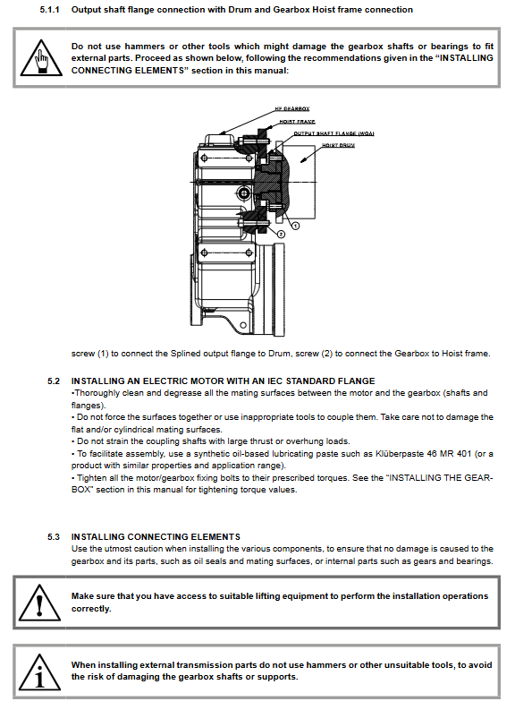
HF specific winch connection structure: schematic diagram of bolt connections between output flange and drum, gearbox and winch frame, distinguishing between two sets of bolts.
5.2 IEC flange motor assembly
Clean the mating surface and prohibit hard tapping; Matching surface coating and paste; Tighten the bolts to the specified torque; Excessive axial/radial loads are not allowed to be applied to the coupling.
5.3 Installation of connectors
Do not hammer the wheel hub or transmission components during installation; The connecting parts can be preheated moderately, but oil seal insulation protection must be done well; All external radial and axial loads must be calculated and confirmed during the selection stage; Transmission components without axial positioning must be equipped with axial limit devices.
5.4 Coating surface protection
Cast iron box factory primer anti-corrosion grade C2 (RAL7042 gray); Protect nameplates and oil seals during painting operations; Spray painting is prohibited on the installation mating surface; Contact the manufacturer before spraying control components.
5.5 Lubrication
HF with LO factory pre filled oil configuration: replace the ventilation plug with a closed plug during transportation, and be sure to replace the ventilation plug before putting it into operation;
Use a 25 μ m filter for refueling; It is strictly prohibited to mix different grades of oil products; The replacement of oil must be thoroughly emptied and the tank must be flushed; The oil must be extreme pressure EP gear oil;
Oil level confirmation: The equipment is in the actual working installation position, and the oil level is at the middle of the sight glass, the oil dipstick mark, or the oil level hole until the oil is discharged;
Reference fuel consumption for each machine base (unit: L)
Model H2 H3 H4
HF40 5.0 3.5 3.5
HF70 8.0 6.0 6.5
HF125 19.0 14.0 14.5
Provide a recommended list of synthetic oils, mineral oils, and lubricants (PAG, PAO base oils); Kl ü ber series lubricating grease); Legend of symbols for vent plug, oil level plug, and drain plug.
5.6 Pre operation inspection
The reducer is a component, and the entire machine must comply with the Machinery Directive 2006/42/EC before it can be started;
The installation position is consistent with the nameplate; Power supply grounding complies with EN60204-1;
The oil level is normal and there is no leakage; Remove all attachments during transportation and restore them to their original state; Protective components are installed in place;
Check for any abnormal noise or vibration after startup; Recheck the torque of all key bolts (expansion discs, flanges, motor flanges, support bolts) during the first 100 operating hours.
Maintenance and upkeep
Maintenance must be powered off and locked; Waiting for the box to cool down; Warranty period fault repair must be authorized by the service provider; Only original spare parts are allowed; Replace all sealing gaskets during disassembly and assembly; It is recommended to replace the bearings in pairs on the same axis; Repair completed and gear oil replaced;
Long term shutdown is recommended to run without load once a month; Otherwise, rust prevention protection should be done.
6.1 Regular inspection of operational efficiency
Regularly clean the dust in the box; Monitor noise and vibration; Check the motor current; Brake wear inspection;
Check whether the seal and oil plug are leaking oil; Monitor the oil temperature of the casing; Check all fasteners.
6.2 Routine maintenance cycle
The oil change cycle depends on the oil temperature:
Table
Oil Temperature Mineral Oil PAO Synthetic Oil PAG Synthetic Oil
<65℃ 8000h 25000h 25000h
65‑80℃ 4000h 12500h 12500h
It is not recommended to operate continuously for a long time at an oil temperature of 80-95 ℃; Regularly check the oil level, vibration noise, shaft alignment, and motor heat dissipation.
6.3 Oil change process
The equipment is in the working installation position; Place the oil receiving container; Oil release; Clean the drain plug magnet; Replace the sealing gasket; Add the correct type of lubricating oil to the specified oil level; Tighten the oil plug. Waste oil shall be disposed of in accordance with environmental regulations.
6.4 Cleaning
Do not use high-pressure water guns to flush the box body; Prohibit incompatible solvents.
Dismantling
Disassembly of IEC flange motor
Do not pry open the flange when stuck; Tapping can be done on the shaft head of the motor fan end, and an impact extractor can be used to remove the motor to avoid damaging the mating joint.
Troubleshooting
Possible causes and solutions for the fault phenomenon
Bearing temperature too high, oil level too low, oil aging, bearing damage, oil replenishment; Change the oil; Contact an authorized repair shop
The temperature of the box is too high and the oil level is too high; Oil aging; Adjust the oil level due to oil pollution; Change the engine oil
Abnormal noise and gear damage; Bearing clearance/wear; Overload; Oil pollution load reduction; Change the oil; Contact an authorized repair shop
Abnormal noise in the installation area. Loose/damaged installation bolts should be tightened with torque; Replace bolts
Oil leakage level is too high; Adjust the oil level if the seals and gaskets are damaged; Replace the sealing gasket
Difficulty rotating, high viscosity of oil; High oil level; Overload replacement of compatible oil products; Adjust the oil level; Recheck the load
The motor does not rotate and the output shaft does not rotate. If there is internal damage to the gear, please contact an authorized repair shop
Some of the faults are caused by the entire equipment and need to be investigated together with the entire machine.
Scrap disposal
Ensure that the equipment cannot be accidentally started before scrapping;
Hand over to qualified recycling institutions for processing; Lubricants, rubber, plastics and other pollutants shall not be directly discarded;
Even if the appearance is intact, components that have been professionally judged to be invalid are prohibited from being reused.
Explosion view and spare parts list
Provide complete exploded disassembly assembly drawings for HF40, HF70, and HF125;
Include part number, part name (various levels of gears, small gears, input shafts, motor flanges, spacers, bearings, seals, bolts, O-rings, etc.);
Label and adapt to IEC motor bases P90, P100/112, P132, P160;
Includes bearing model, seal size, and fastener specifications for ordering original spare parts.