KUKA LBR Med 7 R800, LBR Med 14 R820 Medical Edition Robot
Product Description
The entire system consists of a robotic arm body, KUKA Sunrise Cabinet Med medical control cabinet, smartPAD-2 teaching pendant, cables, Sunrise. OS Med software, Inside Electrical Med media flange, and optional components.
Hardware structure of robot body
7-axis redundant degree of freedom lightweight articulated arm, with all motors and cables built into the body; Each axis integrates position, torque, and temperature sensors; Overload and high temperature automatic shutdown, restart after cooling down.
Structure: A6/A7 built-in wrist, aluminum joint module, base frame; No CR version of fan exhaust components.
Installation support: ground, ceiling lifting, wall hanging.
Inside Electrical Med special medium flange (mandatory use, cannot be omitted)
Weight 262 g, DIN ISO 9409-1-50-7M6 hole position;
Provide 2 power supplies (maximum 48V DC, 8 A/5 A respectively), analog signals, and 2 CAT5 data communication interfaces;
Equipped with medical insulation design to meet 1 MOPP patient protection.
Designated use and prohibition of misuse
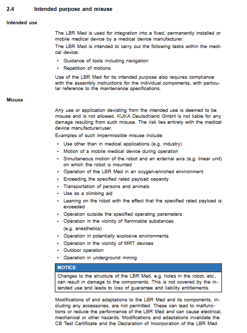
Designated use: Integrated into fixed/mobile medical devices by medical equipment manufacturers to complete tool navigation guidance and repetitive motion execution. Robot design lifespan: 10000 hours of operation time.
Prohibition: Direct use in industrial settings; Oxygen rich environment, anesthesia gas surroundings, explosion-proof environment, and MRI strong magnetic field vicinity; Carrying people and animals; Drilling to modify the structure of the body; Directly connect to patients as BF/CF type application components; Unmanned automatic operation; Outdoor and underground use.
Unauthorized modification of the robot will directly invalidate the CB testing certificate and integration declaration, and all risks will be borne by the medical equipment manufacturer.
Safety (Medical Key Chapter)
Legal and Liability
LBR Med belongs to partially completed machinery and does not comply with medical device regulations; Only after completing the overall integration and medical product compliance assessment can it be put into use.
Holding a CB testing certificate; Only the software version specified in the certificate can be used, changing the software version will cause the certificate to become invalid.
The general safety performance responsibility for the EU medical device MDR 2017/745 Annex I of the entire machine belongs entirely to the medical device manufacturer, and KUKA is only responsible for the robot components themselves.
Not applicable scenarios (manufacturers must conduct risk management assessments): handheld portable medical devices, home environments, defibrillator environments, strong magnetic field environments, unmanned operation.
Personnel Classification
System integrator/medical equipment manufacturer: installation and wiring, risk analysis, safety protection design, issuance of EC compliance declaration, and writing of end-user manuals;
Operators, maintenance and cleaning personnel must be trained and qualified; The maintenance of the body joint module is only allowed to be performed by KUKA official.
The smartPAD-2 teaching pendant is only for integrated debugging and maintenance purposes and is prohibited from being used as a clinical operating device in hospitals; If the teaching pendant is set to be non removable, an external emergency stop that can be reached at any time must be additionally configured.
Work area, danger zone, safety zone
Dangerous zone=robot workspace+stopping distance; Physical protection (grating, fence) is necessary. If there is no physical protection, it must fully meet all the requirements of EN ISO 10218 for human-machine cooperation.
Safety Features
Safety level: EN ISO 13849-1 Cat.3 PL d; EN 62061 SIL2; Test the safety components upon startup and retest at least once every 12 months.
Shutdown type:
STOP 0: Class 0 shutdown, cut off the drive and apply the brake directly;
STOP1 (path maintaining): Slow down and stop along the original trajectory, and cut off the driving brake after stopping.
Operation Mode
Mode description
T1 manual deceleration mode, nominal maximum 250 mm/s; The default configuration of 250 mm/s is not a safety monitoring speed limit; Manually drag and drop without setting the speed limit, relying on security configuration monitoring
T2 manual high-speed mode, teaching prohibited, only used for high-speed program testing
AUT automatic operation mode
CRR safety controller triggers shutdown and resets fallback mode, requiring a teaching pendant
Built in safety hardware: teach pendant emergency stop, three gear enable switch (release/middle effective/fully press panic position; release or fully press will trigger STOP1 path to maintain shutdown, it is strictly prohibited to fix the enable switch with tape).
Configurable external security interfaces: external emergency stop, external path maintenance safe stop, external enable; Axis/Cartesian workspace monitoring, speed monitoring, torque monitoring, collision detection.
Braking test: System forced non closing brake test; Startup/re debugging must be performed; Manufacturers determine cycles in risk management and require daily execution without assessment conditions.
General Safety Measures
IT Security: Manufacturers need to establish a complete information security management system.
Single control point SPOC principle: In T1/T2/CRR mode, the online bus configuration tools (WorkVisual, Sunrise. Wordbench Med) prohibit online modification of programs, outputs, and parameters to avoid personnel danger caused by background changes.
Implant risk: The magnetic field of the motor can interfere with implanted devices such as pacemakers, and the manufacturer’s risk management must be evaluated.
Surface temperature: If the ambient temperature is greater than 28 ℃, the surface temperature of the shell must be evaluated to meet IEC 60601-1 Table 23; Temperature measurement data is available for continuous 7-hour operation at 30 ℃.
The robot body cannot be directly sterilized under high temperature and pressure; A sterile environment requires the use of sterile isolation shields.
Fault handling: Power off, lock and tag, record the fault, and conduct a complete safety function test after troubleshooting.
Transportation pollution: If the robot is contaminated with biological pollutants, it must be returned to the manufacturer with a health status declaration document.
Technical Data
LBR Med 7 R800
Parameter values
Number of axes: 7 axes
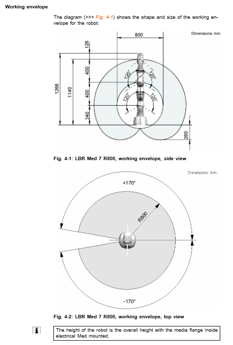
Maximum arm span 800 mm
Rated load 7 kg
Repetitive positioning accuracy ± 0.1 mm ISO9283
Complete machine protection IP54; The flange and tool must be sealed to maintain IP54
The weight of the body is about 23.9 kg
Rated moment of inertia 0.3 kg · m ²; The main body does not allow additional loads to be added
The maximum vertical force of the base is 524 N, and the horizontal force is 240 N
Environment: Working+5~+45 ℃, humidity 20-80%
LBR Med 14 R820
7-axis, rated load of 14 kg, arm span of 820 mm;
The maximum vertical force of the base is 541.2 N; the maximum overturning moment is 281.6 Nm; the maximum torque of A1 is 172.6 Nm;
IP54, Support ground installation, lifting, and wall hanging.
Both models come with complete load curve diagrams, and both load mass and moment of inertia must be verified; The load center of gravity is based on the A7 medium flange end face; The weight of the medium flange is 262g, and the control system automatically calculates it.
Shutdown distance and downtime
Test conditions: Based on PTP point-to-point motion; Provide all axis data for A1-A7 (standard version iiwa is only provided for A4);
Influencing factors: load m, arm extension (0-100%), program speed POV%; Provide a large number of curve graphs;
The manual values are reference averages; The stopping distance of composite motion will be larger, and medical projects must measure the stopping distance/time under actual working conditions.
Internal Electrical Med for Medium Flanges
Interface: X651, X76 two interfaces, including power supply, analog signal CAT5; Complete pin definition;
Insulation concept: Pollution level 2, achieving 1 MOPP patient protection; The shielding layer must not be directly connected to the PE protective ground, otherwise it will damage the medical insulation.
Nameplate Labels
The nameplate is located at the bottom of the robot; The robot with absolute precision calibration will engrave W/A/B/C Euler angle parameters, and installation posture deviation greater than 5 ° will cause the controller to fail to start normally.
Labels are not allowed to be removed without authorization; If the integrated medical device requires label removal, the manufacturer’s risk management must assess the risk.
REACH、RoHS
Meet the requirements of REACH Article 33 and RoHS Directive.
Project Planning
Installation method: Installation of centering positioning pin rack;
7 R800/14 R820: 4 M10 × 30-8.8 bolts, torque 45 Nm, equipped with 2 locating pins.
Absolute precision version robot: The installation posture must be consistent with the posture during calibration; The Euler angles of nameplates A/B/C must be entered into WorkVisual.
Key points of medium flange planning
Must use matching tool connectors; All plugging and unplugging operations are performed with power off;
X651 and X76 pin definitions, shielding grounding rules (critical for medical insulation);
ES adapter: installed on the A3/A5 slot plate, used to fix the external energy pipeline of the tool; Do not fix cables with magnets, as magnetic fields can interfere with torque sensors; Do not connect oxygen or anesthetic combustible mixtures.
PE equipotential grounding: An equipotential busbar must be connected to achieve EN55011 Class B EMC.
Cable: Data cable X21-X31, medium flange power supply cable X76, X651; 4 mm ² equipotential grounding wire.
Transportation
It is necessary to enter the designated transportation posture (A1=0 ° A2=25 ° A3=0 ° A4=90 ° A5=0 ° A6=0 ° A7=0 °), dismantle the tools, and unplug the cables. Before loosening the base bolts, they must be in a transport position to prevent tipping over.
Use original packaging boxes; The two robots have the same outer box size for transportation: length 1180mm x width 780mm x height 560mm.
Lifting points: between A2-A3 and A4-A5; Provide vibration and impact indicators for transportation; The equipment returned due to biological contamination must be accompanied by a health declaration.
Startup and Re Debugging
Installation process: Clean the installation surface → Install the positioning pin → Place the robot → Diagonally tighten the bolts; Check all cables for any pulling or wear.
Disassembly and assembly of slot plate: The specified M2.5 × 6-A4-70-KLF plum blossom screw with a torque of 0.5 Nm must be used; old screws cannot be reused; Friction caused by tilting the slot plate can damage the torque sensor.
Key points for installing ES adapters: Do not use magnetic fasteners; The cable cannot withstand mechanical pulling; Flammable and oxygen medium pipelines are prohibited.
Complete functional testing before power on: safety circuit, emergency stop, enable switch, brake test, grounding continuity.
Maintenance
The body does not undergo regular mandatory disassembly and maintenance; Mainly visual inspection.
Cleaning, disinfection, sterilization
Cleaning and disinfection: use isopropanol (wiping alcohol); Power off and press the emergency stop button for operation;
The robot body does not support high-pressure and high-temperature sterilization (steam sterilization); A sterile environment must use a sterile isolation hood drape, as defined by the medical equipment manufacturer.
Maintenance of medium flange: visual inspection, cleaning and disinfection process consistent with the body; The connector must be unplugged and unplugged when powered off.
Maintenance checklist: labels, cables, plug connections, emergency stop, enable switches, grounding resistors.
Internal maintenance of the joint module is only carried out by KUKA official and cannot be disassembled by users.
Maintenance
On site disassembly is not allowed due to body failure; Replace the robot body as a whole, and conduct a complete set of safety and braking tests after the replacement is completed.
Discontinuation, Storage, and Scrap Disposal
Deactivation: The robot moves to the transport position, disassembles the tool, cuts off the power and unplugges the cable, and protects the connector.
Storage: Dry and dust-free, avoiding condensation; Seal electrical connectors.
Scrap: Joint modules, motors, and circuit boards are treated as electronic waste, and it is prohibited to disassemble motor modules by oneself; Distinguish between the robot body and the medium flange for separate disposal.