KUKA KR 23 SCARA-2 CS SCARA Horizontal Multi Joint Robot
Product Description
System composition
Robot arm body+KR CS Box-2 control cabinet+smartPAD touch teaching pendant+motor cable, encoder cable+system software+options.
Main mechanical structure (4-axis SCARA)
A1/A2 horizontal rotary joint; A3 ball spline Z-axis lifting shaft; A4 end rotation axis.
Main components: main arm, connecting rod arm, ball spline, base frame; Reserved auxiliary load bracket on the arm, with a maximum allowable additional load of 2 kg on the arm.
Electrical: protection circuit, cables for each axis motor I/O、 Ethernet, pneumatic interface;
CR Clean Version: Special dust-proof corrugated tube, negative pressure suction interface, WF series clean connector.
Designated use and prohibition of misuse
Purpose: Fixture/workpiece handling, assembly and transportation, must be used within the environmental parameters specified in the manual.
Prohibition: Carrying people and animals, climbing pedals; Outdoor, explosion-proof, and radioactive environments; Without the permission of KUKA, drilling/modifying the body directly loses the warranty; It cannot be operated independently and must be integrated into the entire equipment.
Security Chapter
Legal responsibility: Declaration of incorporation attached to the entity; The overall risk assessment, EC conformity declaration, CE marking, and terminal operation manual are the responsibility of the system integrator; All risks associated with unauthorized modification of the main body belong to the user.
Personnel classification: integrators, operators, debugging, maintenance, and cleaning personnel; Deep ontology maintenance is only available to authorized personnel of KUKA.
Area Definition
Workplace: reachable range of robots;
Dangerous area=workspace+parking distance, must be physically protected by fencing/grating; Without physical protection, the EN ISO 10218 collaborative robot conditions must be fully implemented.
protective device
A1/A2 configuration with mechanical hard limit; After hitting the hard limit, it is necessary to contact KUKA and prohibit further operation;
A3/A4 configuration body brake release button (power off, manually move Z/R axis); A1/A2 requires software Servo Free to release the brake;
Nameplates and warning labels are strictly prohibited from being removed or altered.
Core Security Points
After power failure, the brake fails and there is a risk of the robotic arm falling; Before maintenance, place it in a safe position and increase mechanical support if necessary; Personnel are prohibited from staying under their arms.
The high temperature of the motor operating casing poses a risk of burns; Electric motors/brakes generate electromagnetic fields, and personnel using active implantable devices such as pacemakers must maintain a distance of ≥ 300 mm.
After the teaching pendant is disconnected, its emergency stop fails, and the disconnected teaching pendant must be moved out of the work area; Enable the switch function to be tested at least once every 12 months.
After modifying hardware, software, and parameters, all programs must undergo low-speed testing in T1 mode; The simulation program also requires T1 testing.
Fault handling: Power off, lock and tag, post fault labels; After the fault repair is completed, conduct a full set of safety function verification.
Live parts operation: If emergency stop is not sufficient, the main power switch must be disconnected and the electricity must be checked; After the controller is powered off, the internal high-voltage capacitor still maintains high voltage for several minutes.
Technical Data
Common basic parameters
Number of axes: 4 axes; Rated load of 10 kg, maximum load of 23 kg; maximum additional load on the arm of 2 kg;
XY repeat positioning accuracy ± 0.025~0.035 mm; Z-direction ± 0.01 mm; R-axis ± 0.01 °;
Noise level<80 dB (A); Only ground installation; Base footprint: 230 × 235 mm;
The working environment temperature ranges from 0 to 45 ℃; Storage -25~+55 ℃; Environmental level 3K22; Low temperature operation requires preheating and deceleration;
A4 flange maximum moment of inertia Iz=1 kg · m ², rated at 0.05 kg · m ²; The load mass and moment of inertia must be verified simultaneously and entered into the KUKA. ControlStudio software; Provide load curve diagrams for each model, with the center of gravity based on the A4 flange end face.
Provide axial force, radial force, overturning torque, and rotational torque for the flange under normal operating conditions and emergency stop impact conditions.
Base load: including the self weight of the body and the load, the base design takes the maximum value.
Shutdown distance/shutdown time: STOP0 and STOP1 provide A1-A3 axis data tables; The manual values are for reference only, and the actual shutdown distance must be measured at the project site under actual working conditions.
REACH Article 33 Compliance.
Key hardware differences between CS regular version and CR clean version
Project KR23-XX-2 CS Industrial Edition KR23-XX-2 CS-CR Clean Edition
Protection level IP20 IP54, ISO cleanliness level 5
Z-direction travel of 200 mm/450 mm, only 390 mm short travel
Corrugated pipe ordinary structure, clean specialized corrugated pipe structure
Connector WEIPU ordinary series WEIPU WF clean series, with added negative pressure suction port AIR0
The weight of the body is about 59-61.7 kg and about 60.9-64 kg
Axis motion range: A1/A2 ± 140 °; A4 ± 360 ° infinite rotation; The A3 itinerary is differentiated by model.
Project Planning
Base design: The user shall design a steel base with a plate thickness of ≥ 20 mm and an installation surface flatness of ≤ 0.4 mm. The maximum allowable inclination of the base is 5 °; Provide a complete base hole diagram.
Cables and interfaces
X30 motor cable, X31 encoder cable; Optional cable length 3 m/5 m/10 m; WEIPU connector;
Minimum bending radius for fixed installation: motor cables ≥ 55 mm; data cables ≥ 45 mm; separate metal cable trays for motor and data cables to ensure EMC;
Base interface: X40 I/O, X74 Ethernet; Multiple sets of pneumatic interfaces AIR0-AIR3 (CR version AIR0 is negative pressure suction); Arm X41 I/O, X94 Ethernet;
Reserved M4/M6 threaded bracket on the arm for installing user pipelines; Do not directly bind cables to corrugated pipes; High flexibility shielded cables are required.
Accelerated wear condition prompt: Long term temperature limit, dust corrosion, continuous full load, monotonic reciprocating motion, external process force, need to shorten maintenance cycle, necessary consultation with KUKA.
Transportation
Transportation posture (must be strictly implemented): A1=-90 °; A2=-90 °; A3=-100 mm; A4=0 °.
There are two ways of handling: forklift handling of original packaging boxes; Use a dedicated fixed plate and M10 lifting bolt crane for hoisting; The length of the suspension rope is greater than 1500mm.
Dismantle tools and tie cables before lifting; Personnel are prohibited from standing under the robot during the entire lifting process; Avoid shock and vibration.
Startup and Debugging (Ground Installation Process)
User base leveling, tilt ≤ 5 °; Pre installed positioning pin; Vertical lowering of the robot body by the crane;
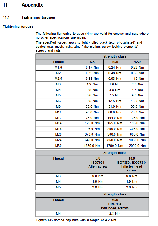
Tighten the base fixing bolts diagonally to the specified torque;
Wiring: equipotential grounding, motor cables, encoder cables; Perform equipotential continuity testing;
Manual axis movement: A1/A2 releases the brake through the software Servo Free; A3/A4 can be manually moved using the brake release button on the main body; There is a risk of A3 falling when releasing the brake, and the load must be manually lifted.
Complete inspection before power on: mechanical fasteners and cables are not pulled or worn; Change the factory default password; Test run all programs in T1 mode.
Maintenance (a large number of on-site executable maintenance items, emergency stop+power-off, locking and tagging must be carried out before maintenance)
Bolts with a strength of 10.9 or higher must be replaced after loosening and cannot be reused.
Maintenance Project Description Consumables
Ball spline lubrication regular version: upper and lower limit coating; The CR clean version requires disassembling the bellows and adding oil; THK AFB-LF lubricating grease
Lubricate the cables in the A1/A2 cable box with Optitemp RB2 grease
Replace the lower corrugated pipe with bearing components, O-ring, and NILOS retaining ring for disassembly and assembly; CR Key Maintenance Component Seal Kit
A3/A4 synchronous toothed belt replacement and tension adjustment use frequency meter TSM alpha-2 to measure tension; After replacement, the Mastering A3/A4 dedicated synchronous toothed belt must be zero calibrated
EDS memory battery unit replacement battery failure and loss of zero point; After replacement, the Mastering dedicated battery kit must be recalibrated to zero
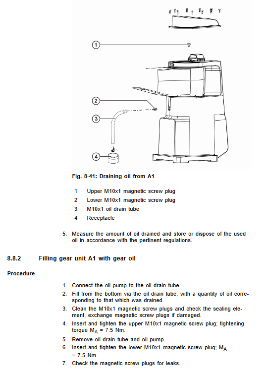
A1 axis gearbox oil change and drain – complete oil injection process specified gear oil
Clean the body, cut off power and stop wiping urgently; Prohibit high-pressure water guns and steam cleaning –
After replacing the bellows, toothed belt, battery, and gear oil, force the robot to perform zero point calibration Mastering.
Maintenance
Repair content: Replacement of upper cover and CR version shaft sleeve cover;
Two sets of zero calibration schemes: ① dedicated calibration fixture; ② Manual calibration of A1-A4 without tooling;
The deep disassembly and maintenance of the main body is only allowed to be carried out by authorized personnel of the warehouse card; The component replacement is completed, and a full set of safety tests and zero calibration are performed.
Chapter 10: Discontinuation, Storage, and Scrap Disposal
Deactivation: Adjust to transport posture; Dismantling tools; Power off and unplug the cable; Disassembly of the main body.
Storage: Dry and dust-free, avoiding condensation; Seal electrical connectors.
Scrap: The motor and RDC/EDS circuit board should be disposed of as electronic waste, and it is prohibited to disassemble the motor gearbox by oneself; Classification of industrial waste for mechanical parts; The appendix lists all grades of sealant, gear oil, and lubricating grease materials.