TDK Lambda Alpha-400 (CA400) Switching Power Supply Installation Instructions
Environmental, Insulation, and Safety Certification
environmental conditions
Project parameters
Working temperature: 0-50 ℃; From 50 ℃ to 65 ℃, the rating will be reduced by 2.5%/℃ (this range is not covered by certification)
Storage temperature -40~+70 ℃
Humidity 5-95% RH, no condensation
Altitude operation -200~3000 meters; storage -200~5000 meters
Protection level IPX0; Type I protection; Weight approximately 2kg, depending on configuration
Dielectric withstand voltage
Original edge ground: 2.25-2.35 kVDC
Primary side – Transformer core/Primary side – Secondary side: 4.25-4.35 kVDC (This test cannot be performed when installing Y capacitor as it may damage the Y capacitor)
Output to each other/output to ground: 500 VDC
Security certification
UL60950‑1、UL62368‑1、CSA; CE、UKCA; CB; with LL/TL/RL filter version supporting IEC60601-1 medical certification. Built in fuse F1:5 × 20mm, F10AH/250V.
Model coding rules
Alpha400 = CA400, Encoding segmentation: basic model+input filter+fan type+output module+functional options
Input filter suffix
TL: minimal leakage current; RL: Low leakage current; LL: Extremely low leakage current (commonly used in medical applications); ML: Medium leakage current; A: A-class input; No suffix: B-class input filter
Fan options
LSF: low-speed fan; RA: Reverse wind direction fan; QF: Silent Fan
Output module: @ Single output/@/@ Dual output up to 5 23 mm slots; Some modules (A, AA, F, G, J, K, R, S, T) occupy 2 slots, while the rest occupy 1 slot. The module includes A/AA/B/BB/C/D/E/EB/EQ/F/G/H/J/L/M/N/P/Q/R/S/T/U/W/Z, and each module corresponds to fixed voltage, current, and ampere turn AT parameters.
Functional suffix options
MF/MFE: Power Failure Detection; MFU: Failure of unbound output power supply; MFV: Adaptation to VME bus power failure;
PA: Parallel current sharing of modules+Module Good signal;
PP: Parallel current limiting;
IN: Output prohibition signal;
RP: Remote voltage regulation (only available for modules ≤ 16V, not supported for modules above 18V);
B/S: Blank space slot.
Electrical input and output specifications
Communication input: 90-264 VAC, 47-63 Hz; maximum input current 7A; surge current < 50A.
The overall power constraint (two conditions must be met simultaneously): ① The total power of all modules is ≤ 400W; ② The total ampere turn AT of all modules is ≤ 80AT;
Special configurations will further reduce the rating:
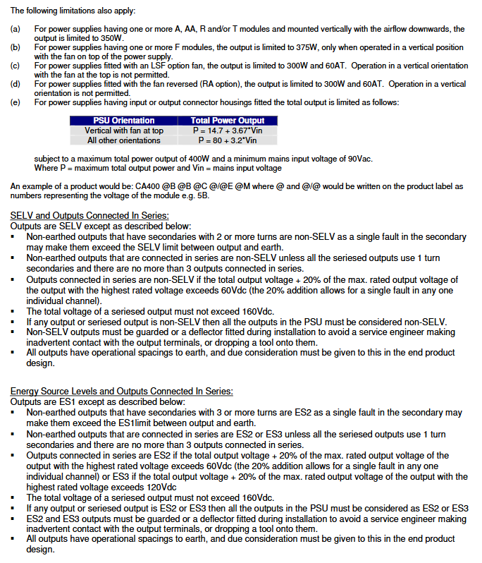
A/AA/R/T module, vertical downward air outlet: maximum 350 W;
F module, fan installed vertically at the top: maximum 375 W;
LSF low-speed fan: 300 W/60AT, vertical installation of the fan on top is prohibited;
RA reverse fan: 300 W/60AT, vertical installation is prohibited.
The parameter list manual of the output module gives a complete description of each module (A ‑ Z): output voltage range, rated current, occupied slot, number of turns, AT ampere turns, current limiting value, and dangerous energy threshold. At the same time, the module derating rules under different slot positions are given. The current of the same module placed in slot 5 will be further derated.
Important limitations of output series connection (SELV/ES1-ES3 hazardous energy classification)
The maximum total DC voltage after series connection is 160 Vdc;
For outputs that do not meet the SELV criteria, the entire machine must be physically protected to prevent accidental touch;
Non grounded output with secondary turns ≥ 2 will exceed the SELV limit under single fault conditions.
Overvoltage protection OVP: If the voltage exceeds the range, OVP will be triggered and all outputs will be turned off; Reset method: Return to normal voltage and disconnect the AC input for 30 seconds.
Remote sensing derating: When Remote Sense is enabled, the output voltage of different modules will lose 0.5V-1.0V voltage drop.
7. Terminal specifications
Communication input: 6.3mm x 0.8mm tinned brass quick connect terminal, 15A; matched with AMP series quick plug connector.
Output terminal:
6.35mm quick connect terminal: 15A;
9.5mm quick connect terminal: 32A;
M5 screw terminal: maximum 100A, recommended torque 2.4-2.6 Nm.
Definition of Hardware Option Interface
MF series (power failure detection) 6-way Molex connector: includes+5V auxiliary power supply, 0V, Power Fail power failure signal, Inhibit disable output, etc. The pin definitions of different sub models MF/MFE/MFU/MFV are different.
PA parallel current sharing options: Module Good module normal signal, remote sampling, star reference point.
PP parallel options: parallel current limiting and sampling.
IN disable output option: External hardware turns off output.
RP remote programming: external analog signal adjusts output voltage.
Drawing content
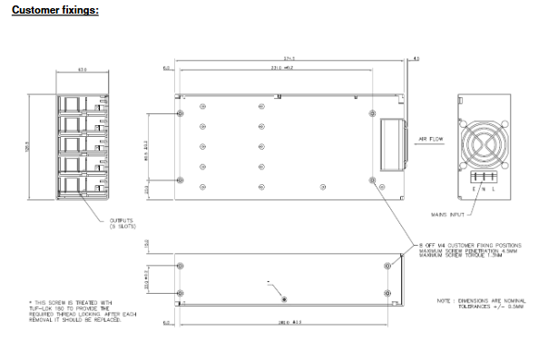
The manual comes with a complete set of PCB layout drawings: main substrate, transformer vertical board, single module PCB, dual module PCB, Twin dual output, J module, L module, S module, T module PCB; Contains various types of connector terminal diagrams; Mechanical dimension drawing of the whole machine: M4 fixing hole, maximum screw insertion depth of 4.5mm.