Installation Instructions for Allen Bradley 1762-OW16 (MicroLogix) Relay Output Module
Product Description
Hardware components
Install buckles up and down; DIN rail lock buckle; Flat ribbon bus connector (female head); Bus protection cover; Terminal doors with identification labels; IO status LED indicator light; Screw terminal block; Pulling ring (used for pulling cables, do not pull the cable body).
Module grouping: Output is divided into two isolation groups: Channel 0-7 is Group 1; Channels 8-15 are Group 2, with electrical isolation between groups.
Adaptation object: MicroLogix1200 controller expansion I/O, connected in series behind the CPU through a flat expansion cable.
Usage environment level: Pollution level 2, overvoltage category II.
Safety precautions before installation
The pins of the ESD protection bus connector are sensitive to static electricity; Before operation, touch a grounded object to release static electricity and wear a grounded wristband; Do not touch the bus pins and board components; Store in an electrostatic shielding bag when not in use.
It is necessary to disconnect the power and disassemble the module. Live plugging and unplugging of the module can generate arcs, which can accidentally drive on-site equipment, cause explosions in hazardous areas, permanently damage the module, and wear out connector contacts.
Dust protection strip: After all equipment installation and wiring are completed, remove the module protective dust strip; Running without tearing it off will cause overheating; Strictly prevent metal debris from falling into the module during installation.
Installation method
Important limitation: 1762 expansion I/O only allows horizontal installation.
1. Heat dissipation gap
Reserve a ventilation space of ≥ 50.8mm (2 inches) around the module.
2. DIN rail installation
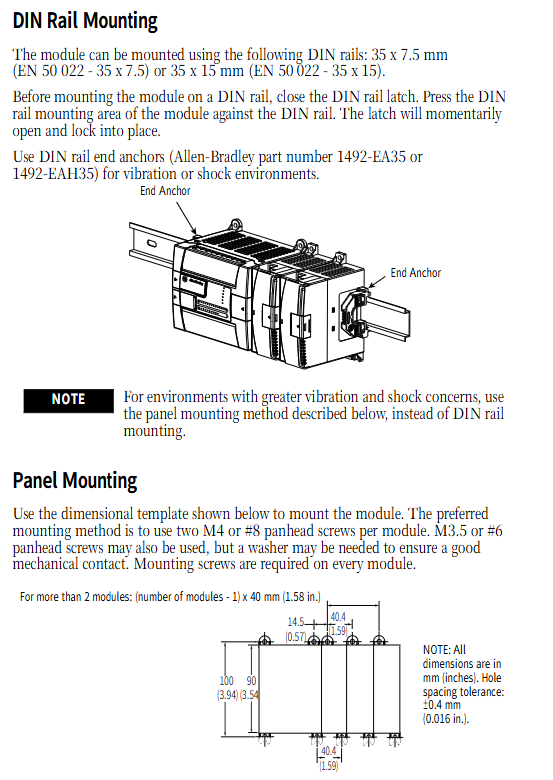
Adaptive rail specifications: 35 × 7.5 mm/35 × 15 mm (EN50022).
Step: Close the DIN lock buckle, press the module card onto the guide rail, and the lock buckle will automatically pop open and lock.
Vibration impact environment: DIN rail terminal block (model 1492-EA35/1492-EAH35) must be used; For strong vibration scenarios, panel screw installation is preferred and DIN rails are not recommended.
3. Installation of panel screws
Screw specifications: Priority M4/# 8 pan head screws; M3.5/# 6 can also be used, with necessary gaskets added.
Size: The width of the module body is 40.4 mm; the total width of multiple modules in series is (number of modules -1) × 40 mm.
4. System bus assembly
After the module is installed in place, use a flat ribbon cable to connect the CPU and expansion module; Disassembling the module can only pull the pull tab on the connector, and it is strictly prohibited to directly pull the ribbon cable.
Mandatory requirements for Class I Div2 explosion-proof locations: The bus connector must be fully inserted and the protective cover must be fastened; The modules are tightly attached without any gaps; Terminal blocks must be installed at both ends of the DIN rail.
On site wiring
1. Grounding
The module needs to be installed on a reliably grounded metal panel; Refer to manual 1770-4.1 “Grounding Guide for Industrial Automation Wiring”.
2. Terminal wiring parameters
Terminal screw torque: 0.90 N · m (8 in lbs).
Wire specifications:
Solid copper wire 90 ℃: # 14~# 22 AWG
Multi strand soft copper wire 90 ℃: # 16~# 22 AWG
A maximum of 2 wires can be crimped onto a single terminal; Support 6.35mm fork shaped cold pressed terminals.
Finger safety cover: It is recommended to keep it when wiring; If the cover plate is removed, it cannot be restored after the wiring is completed.
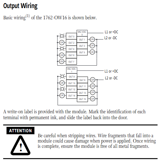
The module comes with a handwritten label strip, and after writing it, insert it into the terminal door for channel identification.
3. Key points of output wiring
Two independent common terminals: OUT0-OUT7 share one common terminal; OUT8-OUT15 share the second group of common; Each group can be connected to an AC or DC power source, and the two power sources can be different.
Inductive loads (relays, contactor coils) must be connected in parallel with surge suppression devices to extend the lifespan of relay contacts.
Wiring must strictly prevent metal debris from falling into the interior of the module.
I/O Memory Mapping and Addressing
Output data file: Output word 0, bit0~bit15 correspond to channels OUT0~OUT15 respectively; This data area only writes (w).
MicroLogix addressing format example: O0: x.0/0
O0: Output data file; X=slot number; The fixed word for this module is 0; /0 digit number (0-15)
CPU body IO: slot number=0; Expansion modules are numbered starting from slot 1.
Complete technical specifications
1. General mechanical environment
Project parameters
Dimensions: 90 (H) × 87 (D) × 40.4 (W) mm; Total height including installation ears 110 mm
Weight approximately 285 grams
Working temperature: 0~+55 ℃; Storage -40~+85 ℃
Humidity 5-95% without condensation
Maximum altitude of 2000 meters
Vibration working at 10-500Hz, 5G; Relay operating condition limit 1.5G
Impact panel installation 30G; DIN rail 40G; Non working 50G
Certification UL508, cULus, CE; Explosion proof Class I Div2 A/B/C/D group
2. Output electrical specifications
Type: 16 normally open relay isolated output, two groups isolated
Working voltage: AC 5-265 V; DC 5-125 V
Backboard consumption: 5V bus maximum 120 mA; 24V bus 140 mA; maximum power consumption 5.6W
Maximum continuous current per channel: 2.5A; maximum common terminal per group: 8A; total module output: 16A; total load: 1440VA
Contact response (resistive load): maximum 10ms for connection and maximum 10ms for disconnection
Minimum conduction current: 10 mA; open state leakage current ≈ 0 mA
Insulation and voltage resistance: assembled backplate 1836VAC for 1 second; 1836VAC for 1 second between groups.
3. Rated relay contacts
Voltage single channel continuous current on/off capability VA capacity
240V AC 2.5A, connect 7.5A/disconnect 0.75A, connect 1800VA/disconnect 180VA
125V DC 1.0A converted to 28VA based on 28VA
24V DC 2.0A connected to 1.2A 28VA
Calculation formula for DC load breaking: Breaking current=28VA/DC voltage; DC<14V, The breaking current is not allowed to exceed 2A. Inductive loads must increase surge absorption.
Use Class I Division 2 in hazardous (explosion-proof) areas
Explosion risk warning:
Do not replace components at will as it may damage the explosion-proof certification;
Modules can only be plugged in or replaced after a power outage;
The module must be installed in a complete protective cabinet;
The bus connector must be fully plugged in and the protective cover must be fastened;
Modules must be tightly attached to each other; DIN rails must be equipped with terminal blocks at both the front and rear.