ABB TZIDC-200 electric pneumatic valve positioner
Product Overview
TZIDC-200 is a microprocessor based intelligent electric pneumatic valve positioner with a modular and compact structure, offering high cost-effectiveness. It can automatically measure control parameters, adapt terminal control valves, reduce debugging time, and achieve excellent control performance.
Working temperature range: -40~+85 ℃
Debugging concept: single button automatic tuning; Comes with mechanical position indicator
Protection: Explosion proof enclosure, while supporting intrinsic safety; Meet SIL2 functional safety circuit requirements.
1.1 Pneumatic Circuit
Using I/P conversion module and pneumatic amplifier, driving 3/3 three-way valve, continuously adjusting actuator inflation and deflation; After reaching the set point, the center position of the three-way valve is closed to reduce air consumption. 4 pneumatic versions: single acting/double acting, supporting fail safe and fail freeze respectively
Fail safe: Power failure, output 1 pressure relief; When double acting, output 2 pressure, and the actuator spring pushes the valve to the safe position.
Fail freeze: When power is lost, the output circuit is closed and the valve remains in its current position; If the compressed air loses pressure, the actuator will release pressure.
1.2 Local Operations
Integrated operation panel for the main body: 2 rows of LCD screens+4 function buttons, completing on-site configuration, commissioning, and status monitoring; It can also be remotely configured through a communication interface.
1.3 Communication Capability
Standard LKS local communication interface;
Optional HART communication, superimposed on 4-20mA analog signal loop;
All communication is based on the HART5.1 protocol.
1.4 Input/Output
Analog input: 4-20mA valve position setting signal;
Digital input DI: Receive control system signals and trigger various protection functions of the equipment;
Digital output DO: Output comprehensive alarm and fault information, following NAMUR standards.
1.5 Modular and Scalable Design
Basic models can be equipped with optional modules in the later stage, supporting hot installation:
4-20mA analog valve position feedback module;
NAMUR digital valve position feedback module;
Emergency shutdown module;
Independent mechanical position indicator;
Proximity switch, 24V micro switch (valve position signal independent of the motherboard).
Attention: The shutdown module and the analog feedback module occupy the same slot and cannot be used simultaneously; The proximity switch/micro switch option must be paired with a mechanical position indicator.
Four installation methods
Straight stroke actuator standard lateral installation: DIN/IEC534 (NAMUR standard lateral installation), matching installation kit; Pipeline joints and air pipes should be provided on-site.
Standard installation of angular actuator: VDI/VDE3845 standard; The bracket kit includes the shaft coupling adapter, which needs to be ordered separately.
Integrated installation with control valve: reserved installation holes on the back of the equipment; The valve position measurement mechanism is built-in and does not require an external trachea.
Customized installation of special actuators: For special actuators, consult ABB for kits.
Operation, Parameters, and Local Panel
3.1 Parameter Classification (Five Major Categories)
operating parameters
4-20mA signal can be split range, with a minimum span of 20%, recommended to be greater than 50%;
Direction of action: signal increase valve open/signal increase valve close;
Traffic characteristics: linear, equal percentage (1:25, 1:50, 25:1, 50:1), supporting 20 point user-defined curves;
Travel limit and two end cut-off function; Bidirectional independent setting of travel extension time (only available in fail safe pneumatic version);
Two point valve position alarm switch point;
Digital output DO: comprehensive alarm, can be set to high effective/low effective;
Digital input DI: configurable: no action, run 0%, run 100%, hold position, disable local operation, lock both local and remote. Trigger condition: Loss of 24V signal (<11VDC).
Parameter adjustment supports automatic adaptive tuning and can also be manually set;
Tolerance zone (factory 0.3%); Dead zone sensitivity (factory 0.1%);
Direction of actuator spring action; Display 0-100% direction matching valve opening and closing.
Monitoring parameter detection: 4-20mA beyond range, valve position exceeding limit, positioning exceeding limit, controller not activated, counter exceeding limit; LCD displays valve position percentage and fault alarm codes; Advanced monitoring requires HART/DTM reading.
Diagnostic parameter statistics of the total number of valve actions and total stroke; Alarm thresholds can be set for predictive maintenance; Can be read/written and reset through HART.
3.2 Local operation panel
Equipped with an openable hinge protective cover, the cover can also be opened in hazardous areas.
Single button automatic operation Autoadjust: One click automatic setting, no need to be familiar with parameters; Automatically identify the zero direction of linear/angular actuators; Custom automatic tuning can also be performed through the panel or HART.
LCD display: Short press the up and down keys to switch between viewing the set value mA, internal temperature of the device, and control deviation.
Communication scheme
DTM component (FDT1.2) TZIDC-200 DTM, integrated into the control system or PC software DSV401 (SMART VISION); Communicate through LKS local interface or FSK HART modem; Parameter downloads are immediately saved to non-volatile memory for immediate effectiveness, and communication does not interfere with control operation.
LKS adapter (RS-232 conversion) LKS interface to RS232, directly connected to PC for workshop debugging and on-site debugging.
Connect the FSK HART modem to any position in the 4-20mA signal loop; Suggest using isolated FSK; The modem is placed in a safe area and can be connected to explosion-proof field equipment.
Key technical data
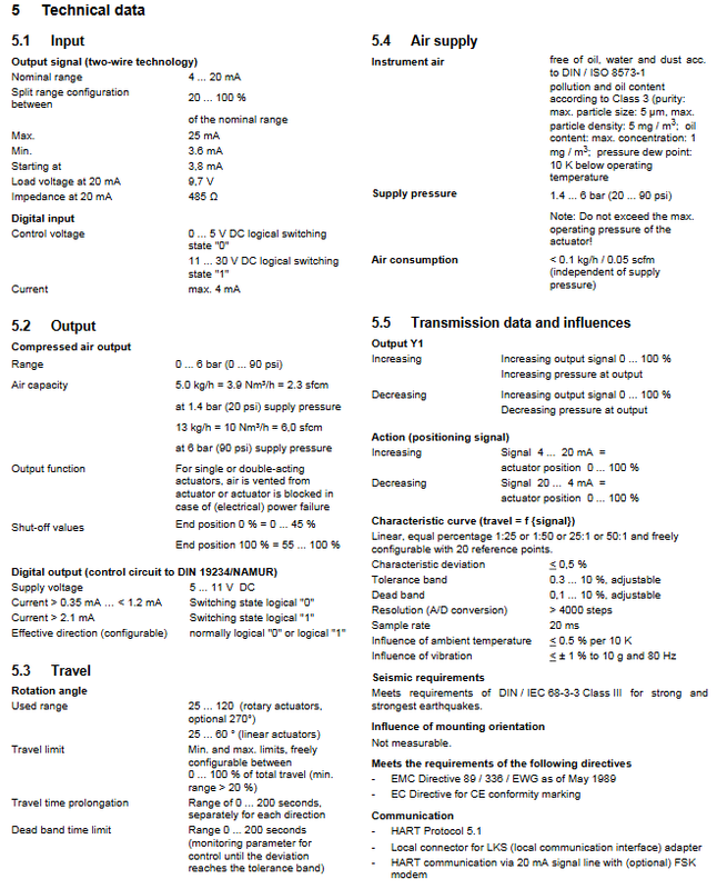
5.1 Input/Output
Analog input two-wire system 4-20mA; minimum startup 3.8mA;
Digital input DI: 0-5V logic 0; 11-30V logic 1;
Air source: Instrument compressed air complies with ISO8573-1 Class 3; Gas supply pressure 1.4-6bar; Steady state gas consumption<0.1kg/h;
Pneumatic output 0-6 bar;
The digital output DO follows the NAMUR DIN19234 standard.
5.2 Itinerary
The angular travel can be extended from 25 to 120 degrees, with the option to extend it by 270 degrees; Direct travel 25-60 °; The itinerary can be limited, with a minimum of 20% of the full itinerary available; Bidirectional independent setting of 0-200s travel delay.
5.3 Performance indicators
Characteristic deviation<0.5%; Dead zone 0.1%; A/D resolution>4000 steps; Sampling period of 20ms; temperature drift<0.5% every 10K; Anti vibration ± 1% @ 10g/80Hz; Meet seismic DIN/IEC 68-3-3 Class III requirements; The installation posture has no impact.
5.4 Environment and Shell
Environmental temperature -40~+85 ℃; When using SJ2-S1N proximity switch, the lower temperature limit is -25 ℃;
Humidity: Maximum working capacity of 95%, annual average allowable condensation; 75% non condensing during transportation and storage;
Cast aluminum shell, IP65 / NEMA4X; Weight 3.0kg;
Electrical interface: M20 × 1.5 or 1/2-14NPT; Pneumatic interface G1/4 or 1/4-18NPT.
5.5 SIL2 Safety Integrity
Suitable for single acting pressure relief pneumatic configuration, according to IEC61508/IEC61511; TZIDC-200 body SFF=85%; Supporting shutdown module SFF=94%, PFDav is lower.
5.6 Explosion proof certification
Having ATEX, FM, CSA, GOST, IECEx; Support explosion-proof Ex d and intrinsic safety Ex ib; Different temperature levels T4/T5/T6 correspond to different allowable ambient temperatures.
Optional modules and accessories
Optional plugin module
Simulate 4-20mA valve position feedback (two-wire): no signal output>20mA as an alarm;
NAMUR digital valve position feedback module: 2 channels can set alarm points;
Emergency stop module (fail safe pneumatic only): independent hardware circuit; 24V loss directly triggers the safe position of the valve; It is mutually exclusive with the simulation feedback module and cannot be installed simultaneously.
External independent feedback kit (mechanical indicator must be included)
NAMUR proximity switch kit;
24V AC/DC micro switch kit (explosion-proof Ex-d version only).
Matching accessories
Installation bracket kits for various linear/angular actuators, explosion-proof cable glands, pressure gauge components, and filter pressure reducing valves; LKS communication adapter, FSK HART modem, DSV401 (SMART VISION) PC configuration software CD.
Electrical wiring, external dimensions
The drawings include terminal overview diagram and pin wiring schematic diagram; Distinguish between basic unit terminals and various optional module terminals (AI analog input, DI digital input, DO digital output, analog feedback AO, proximity switch, micro switch, shutdown module); Provide the location of the grounding screw.
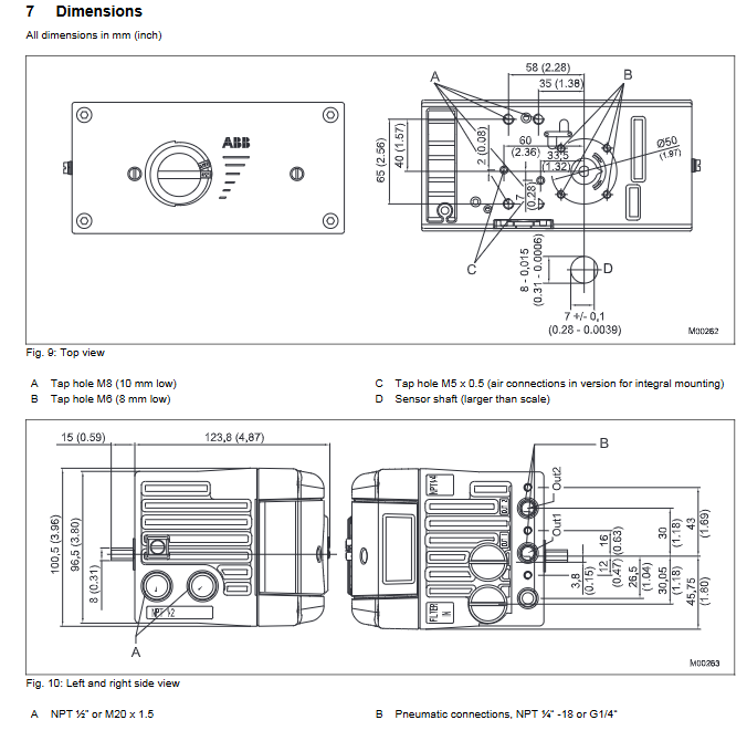
Complete dimensional drawings: top view, left and right side views, bottom view; Installation dimensions for straight and angular travel; Assembly diagram of pressure gauge and filter pressure reducing valve; Unit mm/inch.
Ordering Information
Model series V18348—, multi field code ordering:
The fields include: shell installation form, whether it has a mechanical position indicator, explosion-proof level, pneumatic type (single/double acting, fail safe/fail free), cable thread (M20/NPT1/2), air port thread G1/4 or NPT1/4-18;
Option codes: analog feedback, digital feedback, shutdown module, proximity switch, micro switch; HART parameter setting; Nameplate options;
Certificate options: SIL2 conformity declaration, EN10204 various inspection certificates (CF1/CF2/CF3/CBA);
Accessory order number list: installation bracket, shaft coupler, pressure gauge block, filter pressure reducing valve, explosion-proof gland; Also list the material numbers of the adaptation kits corresponding to mainstream domestic and foreign actuators such as Fisher, Samson, NELES, Hytork, etc.