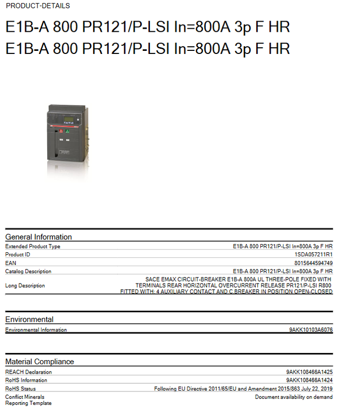
ABB SACE Emax E1B-A 800 air circuit breaker
Product Overview and Model Naming Interpretation
In low-voltage distribution systems, the 800A level frame circuit breaker (ACB) is responsible for the core tasks of protecting the main incoming lines, busbars, and large capacity feeders. The E1B-A 800 PR121/P-LSI in the ABB SACE Emax series is a frame circuit breaker designed according to UL 1066 standards. Its complete model is E1B-A 800 PR121/P-LSI In=800A 3p F HR, with product ID 1SDA057211R1 and EAN code 8015644594749.
For engineers, understanding the model name is the first step in selecting and replacing models. The meanings of each section of the model are broken down as follows:
E1B-A: The B breaking level of the Emax 2 series E1 enclosure belongs to the compact enclosure of the Emax 2 low-voltage circuit breaker family;
800: Rated uninterruptible current In=800 A;
PR121/P-LSI: Release model, PR121/P is a basic electronic release, LSI represents protection function combination – L (overload long delay), S (short circuit short delay), I (short circuit instantaneous);
In=800A: rated current of the release is 800 A;
3p: Three poles;
F:Fixed, Fixed installation;
HR:Rear flat Horizontal, Rear horizontal wiring terminal.
The long description of the product clearly states its configuration: equipped with rear horizontal terminal blocks, PR121/P-LSI 800A three pole fixed release, equipped with 4 auxiliary contacts, and the circuit breaker is in the “open closed” position signal configuration (C breaker in position open closed). The product is classified as a SACE Emax series frame circuit breaker.
Detailed explanation of core electrical parameters
When comparing selection, the following electrical parameters are hard indicators that must be checked item by item:
Parameter project parameter values
Rated uninterruptible current Iu 800 A
Rated operating current Ie 800 A
Rated voltage Ue 690 V
Rated ultimate short-circuit breaking capacity Icu (240 V AC) 42 kA
Rated ultimate short-circuit breaking capacity Icu (480 V AC) 42 kA
Rated ultimate short-circuit breaking capacity Icu (600 V AC) 42 kA
Rated insulation voltage Ui 800 V
Release type PR121/P-LSI (EL)
Short circuit performance level B
Standard UL 1066
Breaking level E1
Number of poles: 3 poles
Current type AC
UL/CSA technical data: According to the UL1066 standard, the breaking rated value is 42 kA at 240 V AC, 480 V AC, and 600 V AC, which means that the circuit breaker has sufficient short-circuit breaking margin in the 480V low-voltage distribution system (commonly known as the 480Y/277V three-phase system in North America) in the North American market. The 42 kA Icu covers the expected short-circuit current level of the vast majority of industrial distribution points.
Durability data: Mechanical durability 20000 cycles (operating frequency 30 times/hour); The electrical durability is 10000 times when Ue ≤ 508 V and 10000 times when Ue=508… 635 V, also based on 30 times per hour. This set of data can serve as a reference benchmark for developing preventive maintenance cycles and life assessments.
Power consumption: Under rated operating conditions, each pole is 65 W, and the total power consumption of the three poles is about 195 W. This power consumption needs to be included in the temperature rise calculation inside the distribution cabinet during thermal design.
Installation form and external dimensions
This model is a fixed circuit breaker that uses a Rear flat Horizontal connection terminal. The external dimensions and weight are as follows:
Product net width: 296 mm;
Product net height: 418 mm;
Product net depth/length: 302 mm;
Net weight of the product: 40 kg.
The overall weight of 40 kg means that the installation support structure and handling scheme of the circuit breaker need to be considered during the design phase of the switchgear; The front projection size of 296 × 418 mm determines the width division of the switchgear, and when designing drawer cabinets or fixed interval cabinets, it is necessary to reserve operating space and busbar connection space based on this.
It is worth noting that the fixed F corresponds to a withdrawable solution – if the later maintenance of the project requires quick replacement of the circuit breaker body without the need for power outage modification of the busbar, the drawer version is a better choice. But for budget sensitive situations with sufficient maintenance windows, the cost advantage of fixed F configuration is obvious.
Functional Analysis of Release PR121/P-LSI
PR121/P is the basic type of Emax 2 series electronic release, powered by a built-in current transformer in the circuit breaker (self powered mode), and can achieve basic protection functions without the need for external auxiliary power supply. The protection function combination “LSI” corresponds to:
L (Long time, Long time overload protection): With inverse time characteristics, it protects cables and equipment from overload damage. The set current In, long time setting Ir1, and time limit tr can be adjusted;
S (Short time, short circuit protection): Short circuit protection with short delay and selective coordination, optional I ² t feature, used to achieve time step selective coordination with lower level circuit breakers;
I (Instantaneous): High short-circuit current quick break protection without delay.
For distribution system designers, LSI three-stage protection is the basic configuration for building a “superior short delay subordinate instantaneous” selective coordination system, suitable for general industrial and commercial distribution. If the project requires advanced functions such as ground fault protection (G function) and zone selective interlocking (ZSI), PR122 or PR123 series release devices need to be considered, which can be easily confused during selection comparison – PR121/P-LSI is a cost-effective basic protection solution.
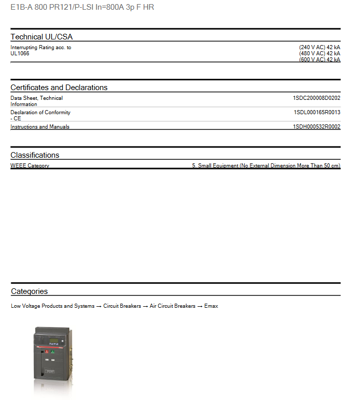
Auxiliary configuration interpretation: 4 auxiliary contacts and position signals
This model comes standard with 4 auxiliary contacts and a circuit breaker “open closed” position signal contact (C breaker in position open closed) at the factory. The practical significance of this configuration for the secondary control loop is as follows:
4 auxiliary contacts: can be used to remotely transmit the opening and closing status of the circuit breaker to the SCADA system, interlock other equipment, drive indicator light circuits, or implement electrical anti trip logic;
Opening closing position contact: Different from ordinary auxiliary contacts for opening and closing states, the “position signal” contact reflects the actual position status of the circuit breaker contact. In situations where the true position of the circuit breaker needs to be confirmed (such as switch operation interlocking, busbar grounding interlocking), it is more reliable than simple mechanism auxiliary contacts.
When ordering spare parts or replacing the entire machine, it should be noted that these auxiliary configurations are part of the order add ons in some series. If accessories such as shunt release, undervoltage release, closing coil, etc. need to be added, the corresponding accessory package should be ordered according to the product ID, rather than replacing the entire machine.
Compliance and Certification System
This product complies with the requirements of the EU RoHS Directive 2011/65/EU and the 2015/863 amendment (July 22, 2019), with RoHS declaration document number 9AKK108466A124 and REACH declaration document number 9AKK108466A1425. Environmental information document number 9AKK10103A6076, conflict mineral report template (CMRT) is available upon request.
The certificates and declaration documents provided with the product include:
Technical Data Sheet: 1SDC200008D0202;
CE conformity declaration: 1SDL000165R0013;
Installation and User Manual: 1SDH000532R002.
When bidding or accepting in the EU market, official documents can be obtained from ABB or its agents with the above document number. In addition, the product is classified as Class 5 “Small Equipment (any external size not exceeding 50 cm)” in the WEEE classification, and should follow the recycling channel requirements of the WEEE directive when scrapped. The product catalog hierarchy is: Low voltage products and systems → Circuit breakers → Frame circuit breakers → Emax.
Typical application scenarios and selection suggestions
Based on its parameter characteristics, typical application scenarios for E1B-A 800 PR121/P-LSI 3p F HR include:
Main incoming or main feeder of North American 480V system: 42 kA@480V The UL1066 breaking capacity is matched with a rated current of 800A, covering the main power distribution needs of medium-sized commercial buildings and light industrial plants;
Generator set outlet protection: 690V rated voltage and E1 breaking level make it suitable for the protection and switching of diesel generator set outlet circuit;
Fixed distribution cabinet scheme: The rear horizontal wiring terminals are arranged in conjunction with the busbar at the back of the cabinet, which is suitable for the busbar under or above the incoming cabinet and contact cabinet.
The recommended checklist for selection replacement is as follows: firstly, check whether the on-site busbar wiring form is rear horizontal terminal (HR). If the original cabinet is vertical or front terminal, the amount of busbar modification needs to be re evaluated; Secondly, verify the demand for breaking ability -42 kA@480V Whether it meets the expected short-circuit current on site; Thirdly, confirm whether the release function combination only requires LSI and whether there is a need to reserve space for upgrading G protection or communication modules; Fourth, confirm whether the number of auxiliary contacts and the configuration of position signals match the original secondary schematic design; Fifth, the replacement construction of the fixed F installation method requires power outage operation and re verification of the busbar torque.