



ABB REF630 feeder protection and measurement device
Four factory preset configurations
Four sets of pre configured templates are provided at the factory, which can be directly modified and used; You can also order blank N configuration to fully customize the engineering logic, and complete configuration, signal matrix, single line diagram, and communication configuration through PCM600 software.
Configuration code usage core features
A open-loop/closed-loop feeder basic feeder protection, including reclosing
Typical configuration of B radial overhead/cable hybrid feeder distribution network overhead lines
C-ring network/mesh feeder with distance protection and longitudinal protection logic
D Mother Union Protection Mother Union Interval Protection Control
N blank configuration with no preset logic, all customizable
Complete protection function
1) Current protection
Three phase non directional overcurrent: low section, 2 sets of high sections, transient period; Supports IEC/ANSI inverse time limit and definite time limit.
Three phase direction overcurrent: low section x 2, high section x 1.
Grounding fault protection (suitable for various neutral grounding methods: ungrounded, through arc suppression coil, resistance grounding)
Non directional grounding protection: low, high, instantaneous;
Multiple instances of directional grounding protection;
Admittance grounding protection, zero sequence power direction protection, instantaneous/intermittent grounding fault protection (dedicated to arc suppression coil system);
Two sets of negative sequence overcurrent protection and phase failure protection;
Three phase thermal overload protection (cable/overhead line thermal model);
Excitation surge detection to achieve second harmonic blocking;
Two sets of circuit breaker failure protection.
2) Voltage and frequency protection
Three phase overvoltage and three-phase undervoltage; Positive/negative sequence overvoltage and undervoltage; Zero sequence overvoltage;
Frequency protection: over frequency, under frequency, df/dt slip;
Low cycle load reduction and load recovery.
3) Advanced Protection (REF630 Features, REF620 None)
Distance protection DSTPDIS: quadrilateral and circular characteristic impedance elements; Support phase to phase and grounding distance; Capable of load suppression and phase selection;
Fault location SCEFRFLO: based on impedance algorithm to calculate fault distance and estimate fault resistance, with an accuracy of about ± 2.5% of the total length of the line; Suitable for radiation type circuits;
Hand failure accelerates SOTF;
Longitudinal protection logic: zero sequence directional longitudinal connection, distance longitudinal connection, supporting permissive and blocking communication logic; Contains weak feedback, current reverse logic, and is compatible with ring networks.
4) General functions
12 sets of multifunctional simulation protection MAPGAPC, customizable logic criteria.
Control function
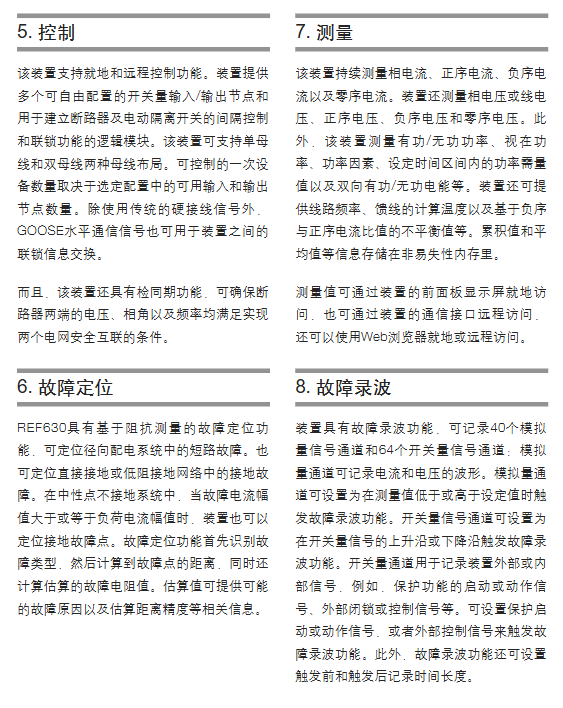
Circuit breaker control (2 sets of examples); Up to 4 isolation switches and 2 grounding switches for control; Support manual device location collection;
SyncRSYN for synchronous/non pressure checks, used for loop closing and parallel operations;
Multiple automatic reclosing (DARREC);
Local remote switching; Support hard contact forced local operation (remote operation for maintenance locking);
Interlocking logic: Supports both hard wiring and GOOSE network signals to achieve interlocking between intervals, reducing the need for secondary cables;
When I/O is insufficient, RIO600 remote I/O can be connected externally, and the number of points can be expanded through GOOSE communication.
Measurement and power quality
Electrical quantity measurement: three-phase current and voltage, zero sequence, positive/negative sequence components; Active power, reactive power, apparent power, power factor; Bidirectional active and reactive electrical energy; Frequency; Load demand.
Power quality monitoring
Voltage fluctuations and voltage imbalance;
Current and voltage harmonics (up to 20 times), THD total harmonic distortion, TDD total demand distortion;
Optional RTD/mA module: connected to external analog sensors such as temperature and pressure.
Recording of waves, events, and faults
Fault recording: up to 40 analog signals and 64 switch signals; COMTRADE standard format, can save up to 100 sets of waveform recordings; Supports analog and switch edge/over limit triggering.
SOE event sequence recording, with millisecond time stamps, non-volatile storage;
Fault report: Save the waveform, amplitude, phase angle, and fault type before and after the fault;
Load curve recording, statistical analysis of long-term load changes.
Equipment monitoring and self inspection
Circuit breaker status monitoring: record opening and closing time, spring energy storage, SF6 pressure, operation frequency, circuit breaker life evaluation, for status maintenance;
Trip circuit monitoring TCS, monitoring circuit disconnection and control power loss during tripping and closing;
PT fuse disconnection monitoring (negative sequence, voltage difference current difference dual algorithm, detecting PT secondary faults, automatically locking voltage related protection);
CT current circuit monitoring, detecting CT secondary disconnection and short circuit, alerting and locking relevant protections;
Self check of software and hardware for the entire device; DC power monitoring;
User permission management: Multi role password, distinguishing between browsing, operation, engineer, and administrator, protecting HMI, WebHMI, PCM600 access security.
Hardware I/O configuration
Analog input
Two types of analog input hardware solutions: traditional transformer CT/VT; Or connect an external RTD/mA module.
Phase current: 1A/5A; Sensitive zero sequence current 0.1/0.5A;
Voltage input: 100-120V;
RTD module: 8-channel RTD thermistor, 4-channel 0-20mA output.
Switching quantity BI/BO
4U chassis: basic 14 in 9 out, expandable up to 32 in 27 out;
6U large chassis: up to 50 inputs and 45 outputs for expansion;
Software adjustable threshold for switch input: 15-221V DC;
Relay output distinguishes between ordinary signal output and high-power TCS output.
Chassis selection: 4U standard chassis; The 6U chassis is used for complex intervals that require a large number of switch inputs and outputs.
Communication capability
Supported protocols: IEC61850 (GOOSE binary+analog GOOSE), DNP3 TCP/serial port IEC60870‑5‑103。
Hardware interface: RJ45 electrical port, LC multimode fiber; ST fiber optic serial port; Debug the network port on the front panel.
Network redundancy: PRP parallel redundancy, HSR high reliability ring network, RSTP self-healing ring network; GOOSE has the highest performance level, with a total transmission time of ≤ 3ms.
Timing: SNTP network timing; IRIG-B hardware B-code timing; The timestamp resolution is 1ms.
Web HMI web interface: browser access, default closed; Can be set to read-only mode to view data event recordings; Cannot perform logical configuration.
System integration: works in conjunction with the COM600 gateway, MicroSCADA Pro, and the entire ABB automation platform System 800xA.
Local Human Machine HMI
320 × 240 monochrome graphic LCD; Support editable single line diagram SLD, displaying primary wiring, equipment status, and real-time measurement;
Multiple dual color programmable LED warning lights; Programmable panel buttons; Open/close hard operation button;
HMI is divided into integrated (4U chassis) and split type: The split type HMI is installed on the cabinet door, and the main body is placed in the low-voltage room of the switchgear, connected using 1-5 meter dedicated cables.
Installation, mechanical, and environmental parameters
Chassis specifications:
4U chassis: height 177mm; 6U chassis: height 265.9mm; depth 249.5mm;
Installation methods: embedded (screen mounted), semi embedded, wall mounted, 19 inch rack; Support installation with RTXP test terminals in 19 inch cabinets;
Protection: Front panel IP40; Backboard terminal IP20; Split HMI front IP42;
Working temperature: -25 ℃ to+55 ℃ for continuous operation; Short term -40~+85 ℃; Storage -40~+85 ℃; The highest altitude is 2000m;
Power supply: AC 100-240V; DC 48‑250V; Maximum power consumption of 35W;
EMC meets the complete set of relay protection immunity requirements of IEC60255; CE and RoHS compliance.
Selection and ordering
The ordering code is a long string of characters, and the key selection items are:
Chassis: 4U (S/U)/6U (T/V); IEC standards; Feeder F;
Analog board (CT/VT, with or without sensitive zero sequence CT);
Number of I/O boards, whether RTD-mA modules are configured;
Communication board: electrical port/fiber LC/ST; Supported protocol combinations;
HMI: integrated/split type (1-5m cable)/no panel;
Functional options: distance protection, fault location, synchronization check, power quality;
Power type; Language (available in both Chinese and English).
Supporting software tools
PCM600: Core Engineering Software; Complete all parameter tuning, signal matrix, application logic, GOOSE configuration, and HMI single line diagram editing; Upload, download, record waves and events.
IED Connectivity Package: Provides data models and SCD related templates for backend system access.
Web HMI: Monitor browsing, does not support configuration.


