ABB DCS400/DCS500B/DCS600, DCF500B/DCF600 thyristor DC drive converters
Product Family Overview
1. DCS (Armature Converter)
DCS400: The smallest compact model in this series, with IGBT integrated excitation unit; Panel/PC debugging wizard with built-in application macros; Please refer to the independent manual 3ADW 000 095 for information.
DCS500B: Upgraded version of DCS500, high-power armature converter; Equipped with SDCS-CON-2 main control board; Equipped with a graphical application designer, 300+software function blocks, text display panel, supporting bus communication, monitoring and debugging. Software version ≥ 21.232 can enable three-phase excitation mode.
DCS600: Based on DCS500B hardware, using SDCS-AMC-DC board instead of COM communication board; Support MultiDrive multi drive and CraneDrive crane drive; Software code S15.xxx (multi drive), S18.xxx (crane).
2. DCF (excitation converter, supplying power to the excitation winding of a DC motor)
DCF500B: Based on the hardware and software of DCS500B, modifying the PIN-1x interface board requires the use of DCF505/506 overvoltage protection unit.
DCF600: Based on the hardware and software of DCS600, it also requires DCF505/506 overvoltage protection and PIN-1x board modification.
The document provides 5 complete system functional block diagrams: DCS500B, DCF500B, DCS600, DCF600, DCS400, clearly showing the power circuit, board, external PLC/PC tools, and DDCS fiber link connection relationships.
Power converter module
1. Power module specifications and mechanical dimensions
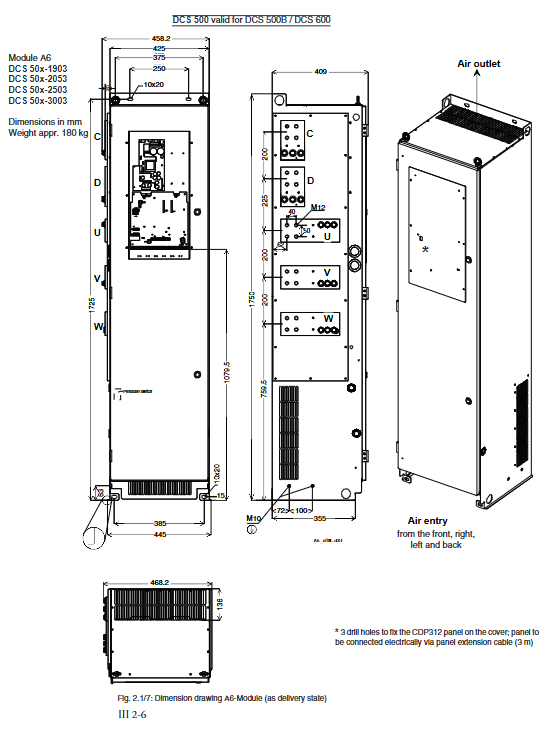
The module is divided into 5 structural specifications: C1, C2, A5, A6, and A7, covering 25A to 5200A
C1: Low power, 25-140A, weight 7.6-11.5kg;
C2: Medium power, 200-1000A, weight 29-42kg;
A5: High power, 900-2000A, approximately 110kg;
A6: Ultra high power, 1900-3000A, approximately 180kg;
A7: Maximum specification, 2050-5200A, approximately 315kg.
The manual provides all module installation drawings, installation clearances, air inlet and outlet directions, and copper bar specifications; A6/A7 are cabinet modules that support left/right power wiring; Ventilation space must be reserved, and hot air needs to be discharged from the cabinet to avoid internal hot air circulation.
2. Internal fuse
The A5/A6/A7 module is equipped with a built-in semiconductor fast fuse (Bussmann 170M series), providing a complete selection table of fuse models and sizes (Size5-10) according to different voltage levels of 400V/500V/600V/690V/790V/1000V.
3. Wiring torque and cable cross-section
Provide the cross-sectional area and bolt tightening torque of power cables/copper bars corresponding to different rated currents under DIN/VDE standards, and distinguish between armature, excitation, and PE protective grounding.
4. Power loss
The total loss consists of three parts: 1) current related losses: thyristors, fuses, and busbars; 2) Voltage related losses: impedance capacitance absorption circuit; 3) Constant loss: electronic board, fan, excitation power supply. Provide a data table for machine type losses and provide a formula for calculating partial load losses.
5. Power unit cooling
All fan models, fan power, air volume, power supply voltage, and lifespan parameters;
C1/C2: Temperature measurement using PTC thermistor for radiator;
A5: Isolation PTC temperature measurement;
A6/A7: Temperature measurement at the air outlet+differential pressure switch, detecting fan faults and air duct blockages; Fault logic: If the temperature rises, an alarm will be triggered first, and if it continues to rise, a fault will be reported and the machine will shut down.
Core control board SDCS-CON-2
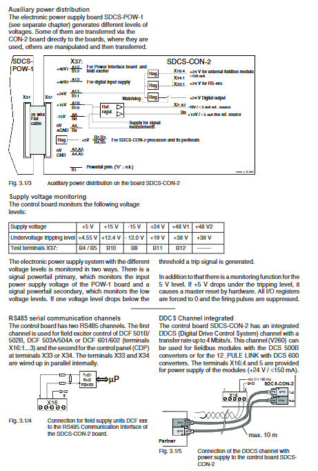
Main CPU board of the whole machine, 80186EM processor+ASIC dedicated chip DC94L01.
Storage: Flash stores programs and parameters; Static RAM stores fault records and operating hours; The backup capacitor can maintain data for at least 8 hours and charge for about 30 minutes.
Seven segment digital display status: distinguish between normal, RAM/ROM error, program stop, download, alarm A, and fault F.
Watchdog: When the program is abnormal, it blocks the thyristor trigger pulse and prohibits writing to flash memory.
Onboard resources
Multi channel analog input and output; Incremental encoder interface;
Digital input DI, digital output DO;
Two RS485 channels (excitation unit, operation panel CDP312);
Integrated DDCS fiber optic interface (4Mbit/s) for fieldbus and multi machine 12 pulse linkage;
Power monitoring: Monitor+5V, ± 15V,+24V,+48V undervoltage, and directly hardware reset the whole machine with+5V undervoltage and turn off the pulse.
Power board SDCS-POW-1
Flyback switching power supply, providing power for the entire electronic system, all DCS500B/600 are universal.
Input AC: 115V/230V and select by dialing code SW1;
Output:+5V, ± 15V,+24V,+48V;
Jumper selection encoder power supply: 5V/12V/15V/24V;
Relay output DO8, contact specification AC250V 3A; Support external backup capacitors to extend power outage retention time.
Power interface board
1. SDCS-PIN-1x (C1 low-power module)
PIN‑11(500V)、PIN‑12(600V); Including pulse transformer, current transformer, RC impedance capacitance absorption, AC/DC voltage measurement, PTC radiator temperature measurement, and hardware coding jumper. As a spare part for DCF excitation, it is necessary to remove the 0 Ω resistor on the board.
2. SDCS-PIN-20x/20xB (C1/C2 medium power)
205B is used for 500V, 206B is used for 600V; supports 2-quadrant/4-quadrant converters; Onboard fuse protection absorption circuit; Rated current, voltage, and 2-Q/4-Q hardware coding can be completed through on-board resistors/jumpers, which can be directly used for DCF excitation without modification.
3. High current A5/A6/A7 architecture: PIN-41/48 pulse board+PIN-51 measurement board
SDCS-PIN-41/48: Pulse transformer board, outputting thyristor trigger pulses;
SDCS-PIN-51: Measurement board, collects armature current, AC/DC voltage, and temperature; Set the rated current and voltage levels by cutting the resistors on the board;
SDCS-PIN-52: Old version, PIN-51 can be directly replaced.
4. Isolation measurement options T90 (AC isolation transformer)+A92 (DC-DC DC transmitter)
Used for high-power models of 2050-5200A, achieving complete electrical isolation between power circuits and electronic circuits; The 12 pulse series system is standard; Provide wiring, gain settings, insulation parameters, and mechanical dimensions.
5. SDCS-CZD-01A Zero Current Detection Board
Used for large inductive loads (excitation, motor generator sets); Simultaneously detect the anode cathode voltage and current of the thyristor, determine true zero current under dual conditions, and enable software parameters.
6. SDCS-MP-1 measuring board
Maintenance and debugging tool board; Plug it into the CON-2 and lead the internal trigger pulse, armature voltage and current, and three-phase voltage out of the test point. The oscilloscope measurement will not interfere with the operation of the equipment.
Digital/Analog IO Board
SDCS-CON-2 comes with non isolated IO; External IO board for electrical isolation, with 4 hardware combinations.
SDCS-IOB-2 (Digital IO) IOB-21 (24-48VDC), IOB-22 (115VAC), IOB-23 (230VAC); 8-way isolated DI, 8-way relay isolated DO; jumper setting input filtering time constant. It must be installed on the DIN rail outside the module.
SDCS-IOB-3 (analog IO+isolated encoder interface) 5-way AI, 3-way AO; isolated incremental encoder interface; Optional jumper for encoder 5/12/24V power supply; Support power supply for PT100/PTC temperature measuring components.
SDCS-IOE-1 IO expansion board with 7 isolated DI channels, 2 AI channels, PTC/PT100 excitation source; DIN rail installation, flat cable connection CON-2, maximum cable length 2m.
Communication board
SDCS-COM-5: DCS500B bus communication board;
SDCS-AMC-DC: Dedicated for DCS600, PC debugging port, external APC application controller;
NDBU-95: DDCS fiber optic splitter.
Excitation unit
SDCS-FEX-1/2 board (with built-in excitation); DCF503A-0050, DCF504A-0050 external excitation; DCF505/506 excitation overvoltage protection unit parameters.