ABB ASTAT ® Crane motion controller
Product positioning and core advantages
ASTAT is a mature fully digital crane drive control system designed for high usage and harsh high-temperature industrial environments, with component grade margins higher than ordinary industrial frequency converters.
1. Hardware structure characteristics
Compact structure: The 1.5MW lifting mechanism control cabinet is only 1.6m high and 1.5m wide, occupying small space and having a light overall weight.
Tolerant to harsh environments: The maximum ambient temperature for the control system module is+70 ℃, and for the thyristor module it is+85 ℃; It can operate stably at grid voltage as low as 70% of rated voltage, and is suitable for weak power supply sites.
Low power loss: The internal power drop is less than 0.5%, and most operating conditions do not require air conditioning cooling. Compared with feedback inverters and chopper resistor inverters, the overall system loss is lower, reducing operating costs.
All digital system: No parameter drift, no need for repeated on-site calibration.
2. Function and usage advantages
Excellent motor torque performance: Excellent torque response, torque capacity not lower than direct power frequency starting of the motor; Closed loop speed control, starting from zero speed, speed regulation is not affected by load, reducing brake and contactor wear.
Potential energy feedback: The energy of the heavy object lowered by the lifting mechanism is fed back to the power grid, saving energy consumption.
Strong anti-interference ability: insensitive to motor cable length and type; Control cables can be laid in the same cable tray as power cables and lighting cables without interference risk.
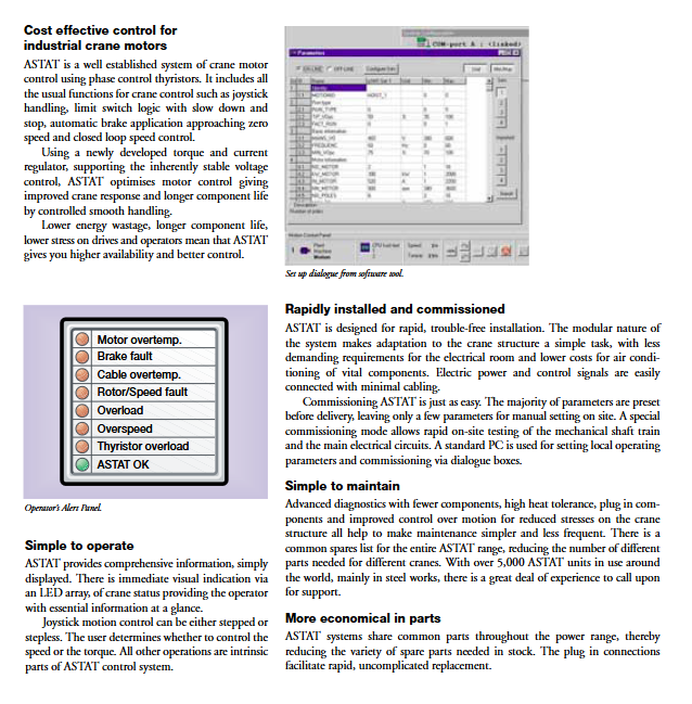
Operation mode: The joystick supports gear/stepless speed regulation, and users can choose between speed control mode or torque control mode. Equipped with standard crane logic such as limit deceleration stop and zero speed automatic brake.
Automation adaptation: Equipped with communication interfaces, sensors such as encoders and laser rangefinders can be directly connected without the need for additional interfaces; Support access to upper level automated monitoring systems.
Easy maintenance: Built in fault diagnosis LED alarm panel, which can intuitively display faults; The module is plug-in type; A large number of universal spare parts in the entire series, with over 5000 sets of on-site applications worldwide and complete after-sales support.
The alarm panel can monitor: motor overheating, brake failure, cable overheating, rotor/speed failure, overload, overspeed, thyristor overload, and system normal status.
Core control principle
System control is divided into stator control and rotor control, similar to cars: stator control is equivalent to throttle, and rotor control is equivalent to gearbox.
Stator thyristor phase controlled voltage regulation, with one pair of thyristors for each phase, continuously and infinitely adjusts the stator voltage to control the motor torque; The forward and reverse rotation of the motor does not require a reversing contactor, and relies on the combination of thyristor conduction to switch the direction of torque. The reversing time is ≤ 10ms. The peak torque is approximately proportional to the square of the voltage.
The rotor resistance adjustment control achieves different mechanical characteristics by changing the external rotor resistance of the slip ring motor, supporting 1-5 rotor characteristics; When the heavy object is lowered beyond the synchronous speed, the energy of the motor is fed back to the power grid. The new version of ASTAT will dynamically optimize motor characteristics based on real-time grid voltage, eliminating the need for manual tuning and reducing motor current. The renovation project can reuse the original rotor resistance.
DSP Digital Signal Processor Technology
Calculate slip through digital filtering of rotor voltage to achieve encoder free speed detection (virtualizing the slip ring motor as a pulse encoder);
Calculate the output torque of the shaft;
Switching algorithm for rotor contactor to suppress stator current surge;
The response time of the current/torque regulator is 3.3ms, and the torque reversal limit is 10ms, balancing response speed and crane safety.
System hardware architecture
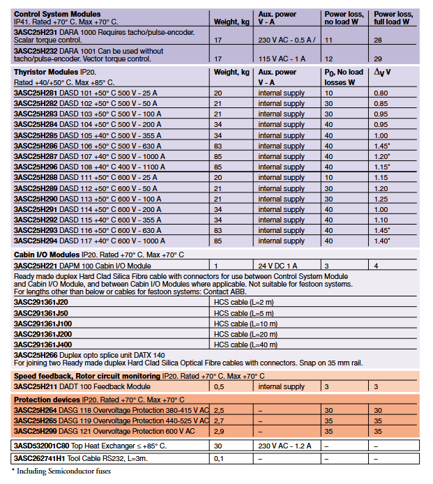
Module Code Module Name Function Description
DARA control system module core control board, DARA1000 (speed generator, scalar torque); DARA1001 (vector torque, supports encoder free rotor speed detection), with digital IO, analog IO, RS232/RS485 communication
DASD thyristor power module main power phase control unit, IP20, Current 25-1100A (can be connected in parallel to 2200A)
DAPM cab I/O module cab control lever, alarm indicator panel; Fiber optic cables can be connected to the main control up to 150m away; When the budget is limited, it can be omitted and the control switch can be directly connected to the main control
DADT100 rotor adaptation feedback module collects rotor voltage to achieve encoder free speed measurement and rotor status monitoring
DASG overvoltage protection module suppresses voltage spikes, detects phase sequence and supply voltage
PC tool: ordinary Windows computer, RS232 interface connection, used for parameter setting, debugging, and fault diagnosis, only for parameter configuration, no programming required.
Key electrical and environmental technical data
Main power supply: 380-600V AC three-phase 50/60Hz, allowable working voltage 70% -110% rated voltage
Rated current: 25~1100A, maximum 2200A for module parallel connection; short-term 2.5 times rated current for 6 seconds
Control power supply: System module 115/230V AC; Cabin I/O module 24V DC
temperature
DARA/DAPM module: maximum+70 ℃
DASD thyristor module: rated reference 40/50 ℃, maximum+85 ℃; If the temperature exceeds the reference temperature, the current will be reduced by 1.2%/K
Pollution level: Following EN60664, different modules support pollution levels 2-4; Adopting encapsulation coating to adapt to harsh microenvironments.
Motor adaptation: The motor stress is equivalent to direct power frequency starting, and ordinary motors do not need to add filters.
Parameter grouping
The parameters are divided into 19 parameter groups: equipment identification, operating type, motor parameters, configuration, brake, speed feedback, speed regulator, current torque regulator, rotor resistance, drum cable, mechanical overload, loose rope, soft limit, rotor monitoring, positioning system, etc.
Drawing templates: Printed manuals are provided, and DXF electronic files are also available on the tool CD.
Order Material List
The document provides complete material part numbers:
DARA control system module: DARA1000, DARA1001, IP41, weight 17kg.
DASD thyristor power module: multiple specifications, covering 25A to 1100A, supporting two voltage levels of 500V/600V, IP20。
DAPM100 cab IO module; Fiber optic cable (2-40m), fiber optic fusion splicing unit DATX140.
DADT100 rotor feedback module; DASG series overvoltage protection unit; Top heat exchanger; 3-meter RS232 debugging cable.
Key selection points
DARA module: 1 per set of institutions; Need vector torque/no encoder speed measurement option DARA1001; Use a speed generator to select DARA1000.
DASD thyristor module: 1 unit per mechanism, allowing 2 units to be connected in parallel without reducing current; Higher than the reference temperature requires a decrease in current; There is no capacity reduction at an altitude of up to 1000m.
DADT100: When no encoder speed measurement or rotor monitoring is required, one mechanism per set is needed.
DAPM100: 1 per operation station, up to 2 (local+wireless remote control).
DASG overvoltage protection: The entire crane is equipped with one set.
Heat exchanger: Select according to the load current and operating duration CDF by looking up the table; Provide recommended height and width dimensions for the cabinet.
Installation and debugging
Most parameters are pre-set at the factory, and only a small amount of parameter configuration is required on site; Capable of debugging mode, testing mechanical transmission and main circuit.
Cabinet installation: Reserve a 200mm ventilation gap between cabinets, or assemble them as a whole to ensure air circulation.