ABB V-Contact VSC medium voltage vacuum contactor
Product Overview
1. Product Introduction
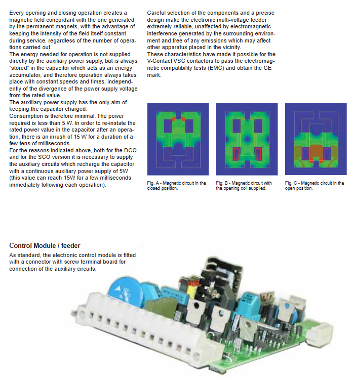
V-Contact VSC is an AC medium voltage vacuum contactor that transplants the MABS permanent magnet drive technology originally used for medium voltage circuit breakers to the contactor and develops a bistable MAC permanent magnet actuator; Driven by a multi voltage electronic feeding module, the internal capacitor energy storage provides opening and closing energy, while the auxiliary power supply only charges the capacitor. The normal power consumption of the whole machine is less than 5W, and the short-term peak value during operation is 15W, which is not affected by power supply voltage fluctuations. The opening and closing speed and time are constant, meeting EMC electromagnetic compatibility and CE certification.
2. Product specification version
Divided into two categories: fixed type and withdrawable type (VSC/P); Two operation modes are also provided:
SCO single command operation: power on and close; When the auxiliary power supply is lost (actively cut off/disconnected), the circuit breaker will open, and the opening delay can be set to 0-5s;
DCO dual command operation: Pulse commands execute closing and opening respectively, and optional undervoltage accessories can be used to achieve power-off opening.
Type Rated Voltage Model
Fixed 3.6kV VSC3
Fixed 7.2kV VSC7
Fixed 12kV VSC12
Withdrawable 7.2kV VSC/P7
Withdrawable 12kV VSC/P12
3. Application Fields
Can be used in industries, buildings, ships, and marine fields; Used for control and protection of motors, transformers, and reactive power compensation capacitor banks; Combined with fuses, VSC7/VSC12 can be used for circuits with a maximum short-circuit capacity of 1000MVA; Adapt to harsh working conditions, obtain DNV and RINA classification society certifications, and comply with IEC 60470 standards.
4. Environmental conditions for use
Environmental temperature: -5 ℃~+40 ℃
Relative humidity:<95% (no condensation)
Standard altitude: ≤ 1000m, altitude correction factor Ka is required for insulation withstand voltage correction above 1000m
Cut off overcurrent: Cut off value ≤ 0.5A, low level of motor switching overvoltage
Maintenance free, can be directly installed on slim lines or traditional prefabricated cabinets, supports direct observation of contact wear, supports remote control, and has a long mechanical and electrical lifespan.
5. Arc extinguishing principle – vacuum arc extinguishing chamber
The main contact operates in the arc extinguishing chamber under extremely high vacuum (13 × 10 ⁻ⁿ Pa); The separation of the dynamic and static contacts in the circuit breaker generates metal vapor to maintain the arc. When the current passes zero, the metal vapor cools down, and the insulation strength of the medium quickly recovers, achieving arc extinguishing and suppressing operational overvoltage. The arc extinguishing chamber consists of a ceramic shell, a sealing membrane, a metal shielding cover, a moving contact, and a stationary contact.
6. Quality System
The enterprise system has passed the ISO9001 quality, ISO14001 environmental, and OHSAS18001 occupational health and safety systems; The laboratory meets ISO/IEC 17025 standards; Reference can be made to use the REF542plus comprehensive protection control unit in conjunction.
Contactor Selection and Ordering
1. Main technical parameters
Covering VSC3 (320A), VSC7-400A, VSC7-800A, VSC12-400A;
Rated frequency 50/60Hz; maximum operating frequency SCO/DCO can reach 900 times per hour;
AC3 electrical lifespan: 100000 to 500000 cycles; The maximum electrical and mechanical lifespan under rated current is 1 million to 2.5 million cycles;
Short term withstand current of 1 second, peak withstand current, short-circuit closing, and breaking parameters are distinguished by model;
Opening and closing time: 20-30ms;
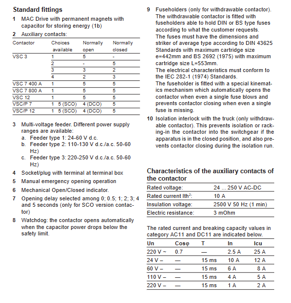
Auxiliary contacts: rated 24-250V AC/DC, 10A, providing multiple sets of normally open and normally closed configurations;
Three voltage levels for the feeding module: Type 1 (24-60V DC); Type 2 (100-125V AC/DC); Type 3 (220-250V AC/DC).
2. Standard configuration
MAC permanent magnet drive+energy storage capacitor;
Multiple sets of auxiliary contacts (different models with different combinations of normally open/normally closed);
Three levels of optional multi voltage feeding units;
Manual emergency disconnection; Mechanical opening and closing position indicator;
The SCO version can be configured with a 0-5s power outage opening delay; Watchdog function (automatic disconnection of capacitor voltage below the safe value);
The pull-out standard fuse holder has the functions of forced opening due to fuse melting and prohibition of closing due to lack of fuse; The chassis of the switchgear is interlocked, and it is prohibited to shake in and out in the closed state.
3. Optional attachments
Includes transmission docking shaft, mechanical/electrical operation counter, DCO version undervoltage delay module, expansion terminal block, fuse adapter kit, non fuse copper bar replacement kit, auxiliary contacts for handcart working/testing position, isolation lock, handcart locking electromagnet, and anti misoperation lock to prevent incorrect insertion of equipment of different current levels (mandatory requirement for UniGear/PowerCube switchgear); Some attachments must be specified when ordering and cannot be added later.
SPECIFIC PRODUCE CHARACTERISTICS
Electromagnetic compatibility and vibration resistance: meets the IEC series EMC standards, is not affected by external electromagnetic interference, and does not emit interference to the outside world; Resistant to mechanical and electromagnetic vibrations; The product undergoes tropical anti-corrosion treatment to adapt to humid and hot salt spray environments.
Installation method
VSC3 fixed type: ground mounted, wall mounted with moving contacts facing downwards, and wall mounted with moving contacts placed upwards;
VSC7/VSC12 fixed type: ground mounted with moving contacts facing downwards; The wall mounted horizontal contact terminal faces downwards.
High altitude correction: For altitudes greater than 1000m, Ka correction is used for power frequency withstand voltage and lightning impulse withstand voltage. The document includes Ka altitude curve and calculation examples.
Guidelines for selecting fuses
(1) Motor circuit
The contactor is responsible for normal switching, and the current limiting fuse is used for short-circuit protection. Overloading must be equipped with an inverse time limit relay, and fuses cannot protect against overload; Provide complete selection steps, combined with motor starting current, starting time, and number of starts per hour, using ABB CMF fuse curve and K coefficient verification; Provide a complete selection example for 1000kW, 6kV motors.
(2) Transformer circuit
The medium voltage side relies on fuse protection and needs to withstand the excitation inrush current of transformer no-load closing. At the same time, it needs to protect the low voltage side winding fault. Provide a selection table of fuse rated current corresponding to transformer power at different voltage levels.
(3) Capacitor switching circuit
The rated current of the contactor shall be at least 1.43 times the rated current of the capacitor; Distinguish between switching between single group capacitors and back-to-back multiple groups of capacitors; Need to limit the peak current and frequency of closing impact; VSC12 switching capacitors must be equipped with overvoltage surge arresters; If the impact exceeds the standard, a series reactor should be connected; Provide the limit value for the product of Ip × f.
Provide various typical primary scheme schematics: transformer power supply, direct full voltage starting, motor forward and reverse rotation, dedicated transformer starting, star delta starting, reactor starting, autotransformer starting, etc.
Overall Dimensions
Provide 2D engineering drawings for all models:
VSC3 fixed type: two types of wiring center distances (65mm standard, 92mm expansion terminal);
VSC7, VSC12 fixed type;
VSC/P7, VSC/P12 pull-out handcart; The drawing includes all installation dimensions such as length, width, height, installation openings, terminal positions, etc.
Electrical Circuit Diagram
Draw separately: fixed DCO, fixed SCO; Complete secondary schematic diagram of withdrawable VSC/P DCO and withdrawable VSC/P SCO; Wiring diagram of electronic control board; Hand cart position and fuse position signal circuit.
Default drawing status: contactor disconnected, circuit not energized;
Complete legend symbol table, defining the meanings of all symbols for terminals XB/XB1, drive unit TR, capacitor CC, opening and closing coils MO/MC, auxiliary contacts BB1/BB2, ready signals PRDY, DR, handcart position contacts, buttons SC/SO, etc;
The product will iterate, and the schematic attached to the physical device takes priority over the sample drawing.