ABB PFEA113 coil tension measurement electronic unit
Measurement Principle
System Composition
PFEA113 host;
Compatible sensors: PFCL301E, PFTL301E, PFRL101, PFTL101, PFCL201, PFTL201;
Optional accessories: PFXC141 field junction box, PXUB201 isolation amplifier, PXKB201 relay board, SD83x series power supply.
Core Competence (Difference 111/112)
A single unit supports up to 4 sensors (A/B/C/D four-way);
6-channel configurable analog output AO1-AO6 (each channel can be configured with voltage/current);
Support 1-roll, 2-roll, and segmented roll applications; Up to 3 PFEA113 units can be cascaded, with a total of 12 sensors connected;
Gain Scheduling: It can store 2 different packet angle gains and adapt to two different packet angle process paths through DI digital input or PROFIBUS switching;
PROFIBUS-DP slave communication; Two analog inputs AI1-AI2 are used for multi machine cascade signal aggregation; 1 digital input DI; 4 isolated digital outputs DO1-DO4;
Equipped with self diagnosis, record the maximum peak load of each sensor; Support signal simulation function for easy debugging of PLC.
Certification: CE, UKCA, UL61010-1, CSA C22.2 No.1010-1.
Mechanical and Electrical Installation
2.1 Mechanical Installation
IP65 wall mounted version: wall mounted, with 13 cable gland heads on the outer shell, requiring sufficient space for opening and maintenance; Fuses and isolation switches must be installed outside the main power circuit.
IP20 rail version: DIN-35 rail, the rail must be reliably connected to PE protective ground; Multiple IP20 devices in the same cabinet must be interconnected with SYNC synchronization terminals (twisted pair/shielded wire) to avoid electromagnetic interference with each other; IP65 version does not require synchronization.
MNS cabinet installation: cabinet splicing, foot fixation, and safety clearance requirements for ventilation around the cabinet and at the top.
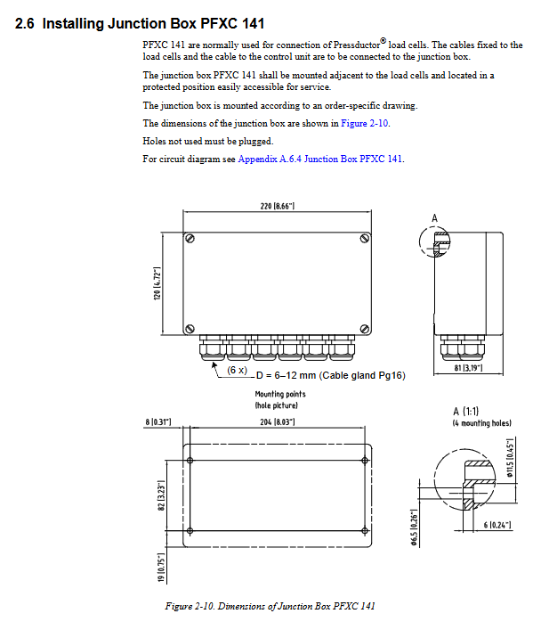
PFXC141 junction box: installed near the sensor, used for collecting multi-sensor cables, and must be sealed without using gland heads.
2.2 Key Wiring Rules
Excitation cable: 2 × 2.5mm ²; Signal cable: shielded twisted pair 4 × 2 × 0.5mm ²; The maximum total cable resistance of the excitation circuit is 10 Ω, and the maximum total cable length is 50m.
The excitation line and signal line are laid separately, with a minimum distance of 0.3m from the power cable, and must intersect vertically at a 90 ° angle.
The shielding layer is grounded at one end, and the length of the shielding stripped wire lead out is ≤ 50mm; it is forbidden to directly press the solid hard conductor to the terminal.
Power supply specifications
IP20:DC 18‑36V;
IP65:AC 85‑264V 45‑65Hz, It also supports external DC24V.
Definition of connector
X1:24V power supply; X2: Sensor excitation output;
X4: 6-channel analog output AO1-AO6; X5: 4-channel digital output DO1-DO4;
X3: Sensor signal input A/B/C/D, AI1-AI2 analog input;
X7:PROFIBUS‑DP D‑SUB; X8: RS232 debugging port.
Signal interface characteristics
AO: Voltage output maximum 5mA; Current output maximum load 550 Ω; Each channel can choose Off/Voltage U/Current I/Bus Output Only;
AI1-AI2: Differential 0-10V analog input, used for cascading and summarizing tension of multiple PFEA113 units;
DO1-DO4: Group isolated output, maximum 0.1A per channel, requiring external 24V power supply;
DI digital input: differential, configurable functions: off, remote zeroing ZeroSet, gain scheduling Gain Scheduling.
2.3 Optional peripheral wiring
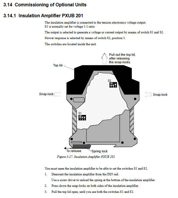
PXUB201 isolation amplifier: realizes electrical isolation of analog signals, DIN rail installation, dip switch gain and bandwidth;
PXKB201 relay board: expands DO output into relay contacts, suitable for loads above 24V AC/DC;
SD83x power module: Provides DC24V for multiple PFEA113 units.
Debugging and Parameter Configuration
3.1 Preconditions for Debugging
Advance preparation is required: sensor model and rated load, roller configuration (1 roller/2 rollers/segmented rollers), whether gain scheduling is enabled, output range, and bus parameters. Panel button logic: return, up, down, OK confirm; Press and hold the OK button for 5 seconds to enter the settings menu.
Two debugging paths: Fast Setup for quick setup (suitable for single roll/double roll basic applications); Complete Setup: Complete setup (segmented rollers, gain scheduling, fine configuration of all outputs).
3.2 Fast Setup Quick Setup
Two methods for setting WrapGain:
HangWeight Hanging Weight Calibration (Recommended): Simulate the path of the tape with a rope and hang a known weight. The equipment automatically calculates WrapGain; The roller must rotate freely to reduce friction errors;
EnterWrapGain manual input: Based on the mechanical installation angle and wrapping angle, manually calculate and fill in WrapGain within the range of 0.5-20.
Quick settings will configure: language, engineering units, bandwidth, zeroing, packet angle gain, analog output mapping, filter time (5/15/30/75/250/750/1500ms optional), and other parameters will use factory defaults.
WrapGain formula: T (actual strip tension)=WrapGain × FR (force measured by sensors).
3.3 Complete Setup Complete Setup Menu System
Presentation Menu Display Menu: Multilingual; Engineering unit (N/kN/kg/lbs/N/kN/kg/m/psi); Strip width (required in units of line tension N/m); Display decimal places.
SystemDefinition System Definition
Load combination: One roll single roll/Two rolls double roll/Segmented roll segmented roll;
Gain Scheduling: After activation, save two sets of WrapGain, DI or PROFIBUS command switches;
SRSF segment roller ratio coefficient: Used to estimate the total tension when there are no sensors at the position of the segment roller.
Object Type Object Type
Standard roll: Two sensors A+B on the same side;
Single Side A/Single Side B measurement: With only one sensor, the internal readings of the device are automatically multiplied by 2 to convert the total tension;
Segmented roller: equipped with 1-4 sensor inputs; Up to 3 PFEA113s, cascaded with AI/AO, supporting up to 12 sensors.
SetNominalLoad rated load: must be consistent with the rated load on the sensor nameplate.
ZeroSet zeroing: Perform zeroing when there is no strip tension on the roller; Compensate for the self weight of the roller and the zero point of the sensor, with a zero adjustment range of ± 2 × Fnom.
SetWrapGain package angle gain: supports weight calibration or manual input; The gain scheduling mode can input two sets of gain values.
AO1-AO6 Analog Output Configuration
Each channel selects a signal source (A/B/A+B/A-B/C/D/C+D/C-D, and the segmented roller also supports AI1 and AI2 signal aggregation);
Set corresponding outputs for high and low tension, as well as high and low amplitude limits; Filter step time;
DO1-DO4 digital output: configurable as tension high/low threshold alarm, high/low band hysteresis, system status OK signal; Support setting thresholds and hysteresis values.
AI1-AI2 analog input: When multiple machines cascade and summarize tension, configure the corresponding tension range and input voltage for the input.
DI digital input: Off/ZeroSet remote zeroing/GainScheduling switching gain.
Miscellaneous menu: PROFIBUS-DP switch, station address, measurement range scaling; Restore factory settings.
Service Menu
Check the firmware version; Record the maximum load of each sensor and the current zero offset Offset; Can reset the maximum load record;
Simulation function: Simulate sensor output for debugging PLC and backend systems. After activation, the red status light will turn on and cannot be zeroed.
3.4 Sensor Verification
Polarity check: When the hand push sensor is subjected to force, the reading should increase positively; Reverse reading requires reversing the polarity of the sensor signal terminal.
Function check: The weights should be loaded with sensors on both sides, and the reading deviation on both sides should be very small.
3.5 PROFIBUS-DP bus function
PFEA113 serves as a DP slave station with station addresses 0-125; Please refer to the appendix for the GSD file; RS485 physical layer;
Loop input buffer: 6 tension measurement values (16 bit complement), fault/alarm status bytes;
Loop output buffer: PLC issues instructions: roll 1 zeroing, roll 2 zeroing, gain scheduling switching;
Bus measurement values can use default scaling or user-defined scaling range and resolution LoadDivision; Bus data filtering and analog output share filter parameters.
Important: The firmware version after SW1.8 has a different scaling logic for the segmented rollers compared to the old version. When replacing the old equipment, the PLC side needs to recheck the scaling factor.
3.6 Multi machine cascade (maximum 12 sensors for segmented rollers)
The first and second PFEA113 use AO voltage output to summarize and output the local tension; Connect AI1 and AI2 to the third host; The third unit has completed the calculation and output of all 12 total tension channels;
All devices must have consistent WrapGain and tape width settings; Filter 5ms (shortest).
Operation
Power on and start, the panel displays: total roller tension, A/B/C/D single channel tension, A-B difference, AO output value, alarm;
Status indicator light: Power supply; Status (green light is normal; Red light alarm/fault/simulation mode);
The alarm information can be viewed directly on the panel, and the fault is cleared and automatically reset;
When a single-sided sensor fails, the object type can be changed to SingleSide single-sided mode to downgrade and continue production.
Maintenance
Preventive maintenance: Regularly check the installation and fastening of sensors, cables, and junction boxes; Remove foreign objects from sensor gaps to avoid measurement errors caused by additional external forces;
Replace controller: All parameters need to be reconfigured;
Replace sensor: ZeroSet must be performed to reset the maximum load record;
There is no firmware upgrade interface, and the firmware version is fixed at the factory.
Fault Tracking
6.1 Fault ERROR (shutdown level, abnormal function)
Flash/EEPROM memory failure → Replace the host;
Power supply error → Check input power supply voltage;
Load Cell Excitation Sensor Excitation Error: Check for broken or short circuits in the excitation circuit, and ensure that the total cable resistance of the excitation circuit is ≤ 10 Ω.
6.2 Warning Warning (without stopping, accuracy affected)
PROFIBUS communication failure;
Multi machine synchronization warning (only for IP20 cabinet with multiple devices, SYNC wiring abnormal).
Typical phenomenon
High reading noise: shielding grounding error, power cable too close;
Zero drift: shield both ends grounded; More than 20 IP20 devices are not connected to SYNC synchronization;
No reading during loading: excitation disconnected, signal polarity reversed.
Downgraded emergency response
One of the sensors is damaged: Modify the Object Type to single-sided measurement mode, and the device continues production.