KBAC-24D/27D/29/45/48 Variable Frequency Drive
Safety points
Must be a certified electrician for installation and maintenance; Strictly prohibited for use in explosion-proof environments; Wear protective goggles and use insulation adjustment tools for live debugging.
Install CE certified RFI filters to meet EMC requirements; It is recommended to shield the signal line, and the shielding layer should only be grounded on the driver side.
It is not recommended to use GFCI leakage protectors. If special firmware needs to be customized, please contact the manufacturer.
Disconnect the main power supply before powering on and ensure reliable grounding; The high-voltage withstand voltage Hi Pot test must use a voltage ramp up/ramp down tester, as direct application of high voltage will permanently damage the driver.
Working environment temperature: 0~45 ℃.
Hardware input and output specifications for each model
Model: AC input motor power range
KBAC-24D single-phase 115/208-230V 1HP and below
KBAC-27D single-phase 115V (maximum 1.5HP)/208-230V (maximum 2HP) 0.5-2HP
KBAC-29 single-phase 208-230V (maximum 2HP)/three-phase 208-230V (maximum 3HP) 0.75-3HP
KBAC-45 three-phase 400-460V 1-3HP
KBAC-48 three-phase 400-460V 1-5HP
Carrier frequency 16kHz; Speed regulation range 60:1; Support output doubling (2X jumper, up to 100Hz/120Hz); PWM sine wave output; The recommended length for motor cables is ≤ 30m, and long cables need to be equipped with reactors.
Chassis and interfaces
Shell: Die cast aluminum, hinged flip cover, black or FDA white sanitary grade shell; Install holes with waterproof cable connectors.
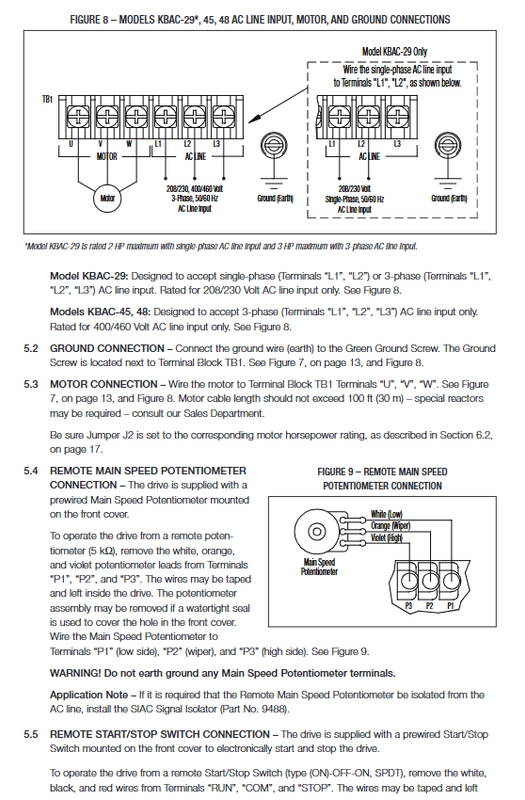
TB1 main terminal block: L1/L2/L3 AC incoming line; U/V/W motor output; Grounding screw.
TB2: Run/Fault relay output (NO/NC/COM).
P1-P3: Speed potentiometer/analog 0-5V input terminal; RUN-COM-STOP start stop terminal; JOG jog terminal.
Panel components: power LED, status tri color LED; Local start stop switch; Main speed potentiometer.
Core functional characteristics
1) Standard Features
Power‑Start ™:> 200% starting torque, suitable for starting under high friction loads.
Slip compensation+static self-tuning+voltage boost Boost, stable speed over a wide speed range.
EICL ™ Electronic surge suppression to eliminate power on surge current.
I ² t motor overload protection (UL certified electronic overload protector)+RMS current limiting to reduce false tripping.
Instantaneous power outage ride through: If the power outage is less than 2 seconds, the speed can be automatically restored, or it can be set to manual restart.
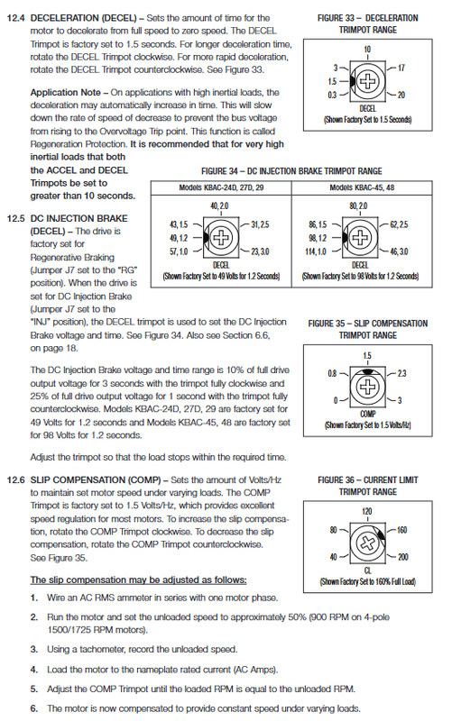
Two braking options are available: regenerative braking (factory default) and DC injection braking.
Run/Fault Relay: configurable for running signal output or fault alarm output.
Supports constant torque CT (mechanical load)/variable torque VT (fan HVAC) modes.
Zero speed holding torque; Support jog JOG function.
2) Jumper Jumper All Functions (J1-J11)
table
Jumper function factory settings
J1 input voltage selection (only 24D, 27D: 115V/230V) 230V
J2 motor horsepower HP gear selection corresponding model default gear
J3 power-off crossing A automatic/M manual restart A automatic
J4 frequency multiplier 1X/2X (2X can reach 2 times the rated motor speed) 1X
J5 motor 50Hz/60Hz nameplate frequency selection 60Hz
J6 Boost Fixed FIX/Adjustable ADJ FIX Fixed
J7 braking mode: RG regeneration/INJ DC injection braking RG regeneration
J8 relay output R=operating signal/F=fault signal R operating
J9 stop contact NO normally open/NC normally closed NO normally open
J10 torque mode CT constant torque/VT variable torque CT constant torque
J11 I ² t protection mode 1 (variable frequency motor)/2 (ordinary motor, HVAC) 1 variable frequency motor
3) Adjustable potentiometer Trimpot
table
Potentiometer adjustment range factory value
MIN minimum speed 0-40% fundamental frequency 0%
MAX maximum speed 70-110%, fundamental frequency 100%
ACCEL acceleration time 0.3-20s 1.5s
Decel deceleration time 0.3-20s; Set braking voltage and time in DC braking mode for 1.5 seconds
COMP slip compensation 0-3V/Hz 1.5V/Hz
CL current limit 40-200% full load 160%
BOOST voltage boost 0-30V/Hz 5V/Hz
JOG jog speed 0-100%, fundamental frequency 35%
Wiring instructions
Disconnect the power supply before wiring; Separate the wiring of power cables and signal cables; Long signal cables use shielded cables, and the shielding is only grounded on the driver side.
Main power supply TB1
KBAC-24D/27D: only connected to single-phase L1-L2; J1 must match the actual input voltage.
KBAC-29: single-phase connection to L1-L2; Three phase connection L1-L2-L3.
KBAC-45/48: Only accepts three-phase 400-460V L1-L2-L3.
Motor wiring TB1 U-V-W: Swap two phases to change direction; Set J2 to match the horsepower on the motor nameplate.
Choose one of the two speed setting methods
Local panel potentiometer;
External 5k Ω remote potentiometer connected to P1/P2/P3;
Isolation of 0-5V DC analog speed regulation; 0-10V requires an external voltage divider circuit; Non isolated signals must be equipped with signal isolator 9488.
start-stop control
Local panel Start Stop switch;
External remote start stop switch, J9 matching contact NO/NC;
Short circuiting RUN-COM can cancel the start stop button and run directly when powered on (dangerous!);
Enable circuit: Connected in series with P2 circuit, closed for operation and disconnected for shutdown.
Run/Fault relay TB2: Passive contact, J8 selects whether to output the running state or the fault alarm state.
The power supply circuit must be equipped with fuses or circuit breakers, refer to the manual table for selection, and it is prohibited to fuse the neutral/ground wire.
Installation and debugging steps
Vertical installation, ensuring ventilation and ambient temperature ≤ 45 ℃; Do not use in explosion-proof hazardous areas.
Set all jumpers (J1 voltage, J2 horsepower, J5 50/60Hz, J10 torque mode, etc.) according to the motor nameplate.
Wiring completed, confirm grounding and fuse configuration; Close the flip cover and tighten the screws evenly.
Power on: The PWR power LED lights up in green. ST status LED tri color light feedback device status.
Normal operation: Green slow flashing; Stop state: yellow constantly on; Overload, short circuit, and overvoltage/undervoltage are indicated with different flashing colors/frequencies to indicate faults.
Instantly press Start to start the motor; Reverse and swap any two phases of the motor U/V/W.
Fine tune each potentiometer according to the load; It is recommended to set the ACCEL/DECEL for high inertia loads to>10 seconds.
Reset method after I ² t fault tripping: ① Press Start again; ② Power off and wait for 15 seconds; ③ Zero the minimum speed potentiometer.
Attention: The heat dissipation of TEFC self fan cooling motor deteriorates at low speeds, and the output torque needs to be reduced; Suggest using a frequency conversion dedicated motor; It is recommended to add a forced fan for cooling at low speeds for ordinary motors.
Optional accessories
Positive stop reverse switch, AC power main switch, run stop jog switch, signal isolator SIAC, Class A RFI filter, multi speed board, DLM handheld programmer+Drive Link PC software, Modbus communication module, waterproof cable connector kit.
Mechanical and Testing
Provide 2 sets of exterior drawings, with KBAC-24D being smaller in size; The remaining 27D/29/45/48 share one set of mechanical dimensions.
Hi Pot Voltage Test: All AC inputs of the driver must be disconnected; The voltage of the tester rises and falls slowly, and direct high-voltage impact can damage the equipment.