
-29%
")
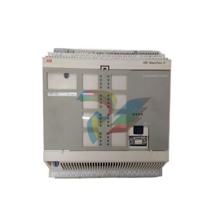
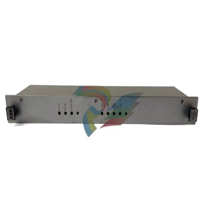
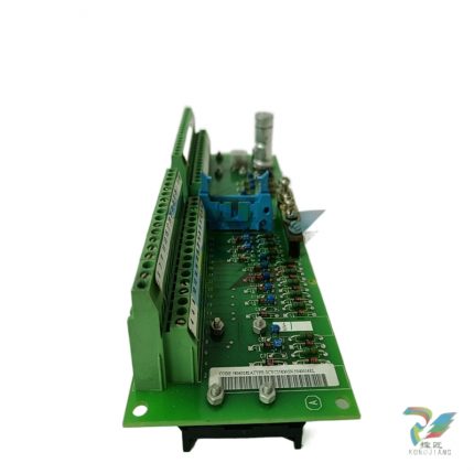
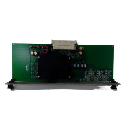
ABB MVME162-010A Embedded Controller Module
Original price was: $4,838.00.$4,437.00Current price is: $4,437.00.个
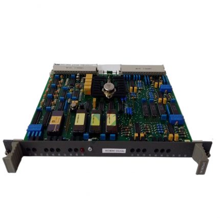
ABB DSTA131 2668180-48/2 Programmable Logic Controller
Original price was: $4,733.00.$4,267.00Current price is: $4,267.00.个
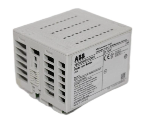
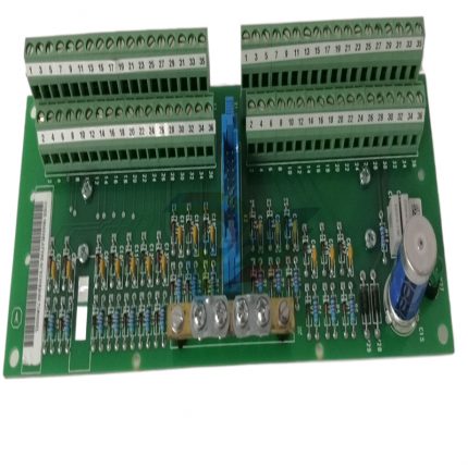
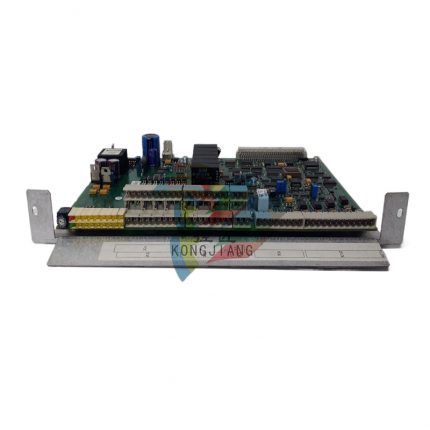
ABB 500BIM01 1MRB150024R0002 Digital Input Module
Original price was: $3,727.00.$2,646.00Current price is: $2,646.00.个
Model identification
500BIM01 1MRB150024R0002
1MRB150024R0002 is the official ABB order number, and 500BIM01 is the module functional model
Module Type
Digital Input (DI) Module
Only used for collecting external digital signals, without output control function
Suitable for PLC systems
ABB AC500 series PLC
It needs to be used in conjunction with AC500 series CPU modules and baseboards, and supports bus expansion
Power demand
Logic power supply: DC 24V ± 10%; Signal power supply: shared with logic power supply
Industrial grade wide voltage design, adaptable to on-site power fluctuations
power consumption
Typical value ≤ 3W
Low power design to reduce overall system energy consumption
Description
ABB 500BIM01 1MRB150024R0002 Digital Input Module
Basic information of module core
Model identification
500BIM01 1MRB150024R0002
1MRB150024R0002 is the official ABB order number, and 500BIM01 is the module functional model
Module Type
Digital Input (DI) Module
Only used for collecting external digital signals, without output control function
Suitable for PLC systems
ABB AC500 series PLC
It needs to be used in conjunction with AC500 series CPU modules and baseboards, and supports bus expansion
Power demand
Logic power supply: DC 24V ± 10%; Signal power supply: shared with logic power supply
Industrial grade wide voltage design, adaptable to on-site power fluctuations
power consumption
Typical value ≤ 3W
Low power design to reduce overall system energy consumption
Key performance characteristics
1. Signal acquisition capability
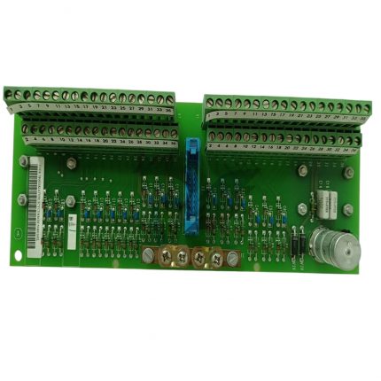
This module has 16 independent digital input channels, each of which can be independently configured with signal types. It supports sensor signal input of PNP and NPN polarities, without the need for hardware jumper switching. Parameter settings can be directly made through programming software, greatly improving the flexibility of on-site installation and debugging. The input signal voltage range is DC 15V-30V, suitable for common 24V DC sensors in industrial fields. The typical input current value is 2.5mA (at DC 24V), which can effectively avoid module damage caused by excessive signal current.
2. Response speed and filtering characteristics
The module adopts a high-speed signal processing chip, and the response time of each input channel can be flexibly configured through software within the range of 1ms-100ms to meet the real-time signal requirements in different scenarios. For high-speed motion control scenarios, a short response time can be set, and for complex interference environments, the response time can be extended to enhance the filtering effect. Built in hardware RC filtering circuit and software digital filtering algorithm can effectively suppress electromagnetic interference (EMI) and radio frequency interference (RFI) on site, ensuring the accuracy of signal acquisition in strong interference environments such as motor start stop and frequency converter operation.
3. Anti interference and reliability design
The module follows industrial grade EMC (electromagnetic compatibility) standards and has passed EN 61000-6-2 (anti-interference) and EN 61000-6-4 (emission) certifications. It has ± 2kV electrostatic discharge (ESD) protection capability and ± 1kV electrical fast transient burst (EFT) protection capability, and can be directly applied to harsh electromagnetic environments in industrial sites. Adopting isolation design, photoelectric isolation is achieved between channels as well as between channels and power supply and bus. The isolation voltage can reach 500V AC (rms), effectively preventing external signal interference from entering the PLC system bus and ensuring the stable operation of the entire control system.
4. Diagnostic and maintenance functions
The module has complete self diagnosis and fault alarm functions, and provides real-time feedback on the working status of the module through LED indicator lights. The power indicator light (PWR) displays the power supply status of the module, and the bus indicator light (BUS) displays the communication status with the CPU. Each input channel is equipped with status indicator lights (DI1-DI16), which intuitively display the signal status of the corresponding channel. When there is an abnormal situation such as power failure, bus communication interruption, channel overcurrent, etc., the module will upload the fault information to the CPU through the bus, which facilitates the operation and maintenance personnel to quickly locate the fault point through programming software and reduce maintenance costs.
Installation and configuration points
1. Mechanical installation
The module adopts a standard DIN rail installation method, with dimensions of 120mm (height) × 100mm (width) × 22.5mm (depth), and can be compactly arranged and installed with other I/O modules, CPU modules, and power modules in the AC500 series, saving control cabinet space. During installation, it is necessary to ensure that the bus interface at the bottom of the module is fully engaged with the AC500 motherboard to avoid communication failures caused by poor contact. At the same time, at least 5mm of heat dissipation space should be reserved around the module to prevent high temperature environments from affecting module performance.
2. Wiring specifications
The module adopts spring type terminal blocks, supporting wire connections of 0.5mm ² -2.5mm ². Wiring does not require tools, and wire insertion and removal can be completed by pressing the terminal, improving wiring efficiency. When wiring, it is necessary to distinguish between power terminals (L+, M) and signal terminals (DI1-DI16, COM). The common terminal (COM) of all input signals must be reliably connected to the negative terminal (M) of the module power supply to ensure the integrity of the signal circuit. For long-distance signal transmission (over 10m), it is recommended to use shielded wires and ground the shielding layer at one end to further enhance anti-interference capability.
3. Software configuration
The module needs to be configured through ABB AC500 series dedicated programming software CODESYS or ABB Automation Builder. In the software, you need to first create a project and select the corresponding CPU model, then add the “500BIM01” module and match the order number “1MRB150024R0002” to complete the bus mapping between the module and the CPU. Subsequently, the response time, signal polarity, and other parameters of each channel can be configured according to on-site requirements, and the real-time monitoring of module operation status and channel signal values can be achieved through the software’s online diagnostic function.
Application scenarios and precautions
1. Typical application scenarios
-Manufacturing production line: Collecting signals from conveyor limit switches, photoelectric sensors, buttons, etc. to achieve process linkage control.
-Energy industry: used for monitoring the switch status of substations and photovoltaic power stations, such as collecting the on/off status of circuit breakers and isolating switches.
-Chemical and Metallurgical: Collect signals such as temperature switches, pressure switches, and liquid level switches around the explosion-proof area to ensure production safety.
-Intelligent building: Monitor signals such as access control switches, fire alarm buttons, and fan start stop status to achieve building automation control.
2. Precautions for use
1. The module needs to be used under specified environmental conditions: working temperature is -25 ℃~+60 ℃, relative humidity is 5%~95% (no condensation), avoid installation in high temperature, high humidity, dusty or corrosive gas environments.
2. It is strictly prohibited to plug or unplug wiring terminals or bus interfaces while the module is live, in order to avoid arc damage to the internal circuit of the module.
3. The input signal voltage should not exceed DC 30V, otherwise it will cause permanent damage to the channel. During on-site debugging, it is necessary to first confirm that the sensor output voltage meets the requirements.
4. Maintenance of module faults should be carried out by professional technicians. It is prohibited to disassemble the module casing without authorization to avoid damaging the isolation performance or causing safety hazards.
Additional information
| Weight | 3.4 lbs |
|---|---|
| Dimensions | 372 × 346 × 26 in |
Reviews (0)
Shipping and Delivery


Reviews
There are no reviews yet.