
-16%
")
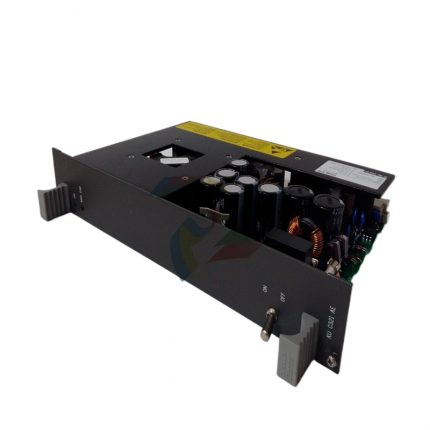
ABB PFSA140RULLM7A 3BSE006503R1 safety relay module
Original price was: $7,383.00.$7,084.00Current price is: $7,084.00.个
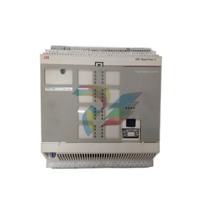
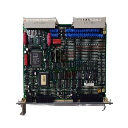
ABB MVME162-010A Embedded Controller Module
Original price was: $4,838.00.$4,437.00Current price is: $4,437.00.个
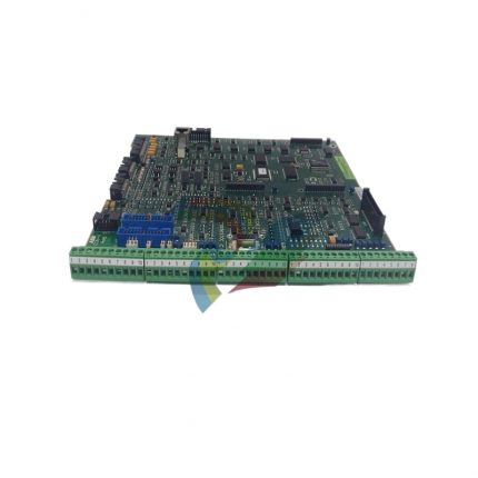
ABB PFSA140RULM1I 3BSE06503R1 drum power supply device
Original price was: $4,838.00.$4,084.00Current price is: $4,084.00.个
The MC68040 processor equipped in the module integrates integer operation units, floating point operation units (FPUs), and memory management units (MMUs), among which the floating point operation units can efficiently handle complex mathematical operations involved in industrial control, such as PID regulation, data filtering, etc., with an accuracy of IEEE 754 standard. At a frequency of 25MHz, the integer operation speed can reach 20 MIPS (millions of instructions per second), and the floating-point operation speed can reach 10 MFLOPS, which can meet the real-time requirements of multitasking concurrent processing scenarios, ensuring fast response and execution of control instructions.
Description
ABB PFSA140RULM1I 3BSE06503R1 drum power supply device
Basic information of device core
Model identification
PFSA140RULLM1I 3BSE06503R1
3BSE06503R1 is the official exclusive order number of ABB, PFSA140RULLM11I is the functional model, indicating the power supply specifications and adaptation scenarios
Device Type
Industrial grade drum dedicated power supply device
Optimization of the characteristics of the conveyor drum drive motor, with load adaptation and protection functions
Input power specifications
AC 380V ± 15%, 50/60Hz three-phase
Adapt to industrial site standard three-phase power supply, with a wide voltage range to cope with grid fluctuations
Output power specifications
DC 48V, Rated output current 140A; supports short-term overload output (120% rated current, continuous for 10 seconds)
Provide stable power for the DC driven drum motor, with overload capacity meeting the motor starting requirements
Protection level
IP54 (shell), IP20 (internal wiring terminal)
Dustproof and splash proof design, suitable for dusty and humid industrial site environments
Overall dimensions
600mm (height) x 450mm (width) x 250mm (depth)
Modular structure design, easy to install inside the control cabinet or independently installed on the ground
weight
About 35kg
Adopting high-strength steel plate shell to enhance structural stability and impact resistance
Key performance characteristics
1. Efficient and stable power conversion capability
The device adopts advanced three-phase bridge rectification+PWM (pulse width modulation) voltage stabilization technology to convert the input three-phase 380V AC power into 48V DC power. The power conversion efficiency is over 92%, effectively reducing energy loss and minimizing the device’s own heat generation. Internally integrated high-precision voltage regulation module, the output voltage fluctuation range is controlled within ± 0.5V, ensuring stable speed of the drum drive motor and avoiding uneven conveying speed caused by voltage fluctuations. At the same time, the device has excellent load adjustment rate (≤ 1%), and even in the scenario of sudden load changes when multiple rollers are started simultaneously, the output voltage can still remain stable, ensuring the synchronous operation of the conveying system.
2. Comprehensive security protection mechanism
To ensure the safe operation of the device and drum motor, multiple protection functions are integrated to form a comprehensive safety guarantee system: firstly, overload protection. When the output current exceeds 120% of the rated value and lasts for 10 seconds, the device automatically cuts off the output and alarms to prevent the motor from burning out due to overload; The second is short-circuit protection, which adopts a dual design of fast melting and electronic current limiting. The short-circuit response time is ≤ 1ms, and the fault circuit is quickly cut off to prevent the fault from expanding; The third is overvoltage/undervoltage protection. When the input voltage exceeds the range of AC 380V ± 15% or the output voltage rises abnormally, the device triggers protection and shuts down; The fourth is over temperature protection, which is equipped with a temperature sensor inside. When the temperature of the core components of the device exceeds 85 ℃, it will automatically reduce the capacity and run. When the temperature reaches 95 ℃, it will shut down to prevent damage to the components due to high temperature. In addition, the device also has anti reverse protection function to prevent damage to the motor or device caused by incorrect connection of the positive and negative poles of the output terminal.
3. Industrial grade environmental adaptability design
In response to the harsh operating environment of industrial sites, the device has undergone enhanced design in terms of structure and component selection. In terms of temperature adaptability, the working temperature range is -10 ℃~+55 ℃, and the storage temperature range is -40 ℃~+70 ℃, which can adapt to extreme temperature scenarios such as cold mines and high-temperature metallurgical workshops; The humidity adaptation range is 5%~95% (no condensation), and circuit boards treated with moisture-proof coatings can effectively resist the erosion of humid environments. In terms of anti-interference performance, the device has passed EN 61000-6-2 (industrial environment anti-interference) and EN 61000-6-4 (industrial environment emission) certification, with a surge impact protection capability of ± 2kV and an electrical fast transient pulse group protection capability of ± 1kV. It can effectively resist electromagnetic interference generated by on-site frequency converters, high-power motors and other equipment, ensuring its stable operation.
4. Flexible control and communication capabilities
The device supports two modes: local control and remote control, meeting the operational needs of different scenarios. Local control achieves functions such as start stop and parameter setting through buttons on the device panel. It is equipped with a high-definition LCD display screen, which displays real-time information such as input/output voltage, current, device temperature, and operating status. When there is a fault, the fault code can be directly displayed, making it easy for on-site personnel to quickly troubleshoot. In terms of remote control, the device integrates RS-485 communication interface, supports Modbus RTU communication protocol, and can be connected to PLC or industrial control system to achieve remote start stop control, parameter reading and modification, fault information uploading and other functions, facilitating centralized monitoring and intelligent management of the conveying system. In addition, the device reserves an expansion interface for PROFINET communication module, which can be upgraded to industrial Ethernet communication according to user needs, improving communication speed and networking flexibility.
5. Convenient maintenance and diagnostic functions
The device has a complete self diagnosis and maintenance friendly design: firstly, it has a built-in fault memory function, which can store the type, occurrence time, and operating parameters of the last 10 faults, and can query fault records through panel buttons or communication interfaces; Secondly, key components such as rectifier bridges, filtering capacitors, and fuses are designed modularly for quick replacement; The third is that the device is equipped with an independent ventilation and heat dissipation system, which adopts a combination design of dust-proof fan and heat dissipation fins. The fan speed can be automatically adjusted according to the temperature of the device, ensuring heat dissipation effect and reducing noise. At the same time, the fan has a fault alarm function to remind maintenance personnel to replace it in a timely manner. In addition, ABB provides specialized diagnostic software that can be connected to devices via USB interface for more accurate parameter configuration, performance testing, and fault diagnosis.
Installation and configuration points
1. Mechanical installation
The device supports two installation methods: one is installation inside the control cabinet, ensuring that the internal space of the control cabinet meets the device’s heat dissipation needs. At least 150mm of heat dissipation space should be reserved between the device and the inner wall of the control cabinet and other equipment. The control cabinet should be equipped with ventilation fans or heat dissipation holes to ensure air circulation inside the cabinet; The second is independent ground installation, which requires the use of dedicated installation brackets for fixation. The brackets should have sufficient load-bearing capacity, and the installation ground should be flat and sturdy to avoid vibration transmission to the inside of the device. Regardless of the installation method used, it is necessary to ensure that the device is securely installed to avoid displacement or loose wiring caused by vibration during the operation of the conveying system. During the installation process, attention should be paid to protecting the device casing to avoid collisions that may cause a decrease in protective performance.
2. Electrical connection
Electrical connections must strictly follow the device wiring diagram and be operated by professional electricians to ensure safe and reliable connections. Firstly, for input power connections, copper core cables with a cross-sectional area of ≥ 16mm ² should be used to connect three-phase 380V power supplies. When wiring, it is necessary to distinguish between L1, L2, and L3 phase wires and neutral wires (N) and ground wires (PE). The ground wire must be reliably grounded with a grounding resistance of ≤ 4 Ω, and a circuit breaker (rated current 200A) should be installed in the input circuit to achieve first level protection; The second is to connect the output power supply, using copper core cables with a cross-sectional area of ≥ 50mm ² to connect the drum motor, ensuring that the cable current carrying capacity meets the 140A rated current requirement. When wiring, it is necessary to confirm that the positive and negative poles of the motor correspond to the output end of the device to avoid reverse connection; The third is the connection between communication and control lines. The RS-485 communication line uses shielded twisted pair cables, with the shielding layer grounded at one end. The control line and power line are separately wired with a spacing of ≥ 100mm to avoid electromagnetic interference. After the connection is completed, it is necessary to check the firmness of the wiring and the correctness of the polarity again. Only after confirming that there are no errors can the power be turned on.
3. System configuration and debugging
Device debugging needs to be carried out step by step to ensure that all parameters match the system requirements: first, check whether the input power supply voltage is around AC 380V before powering on, and confirm that the “emergency stop” button on the device panel is in the pressed state; Secondly, connect the input power supply, release the “emergency stop” button, and the device will enter standby mode. Check whether various parameters are normal through the panel LCD display screen (such as the preset output voltage of 48V); Then, perform no-load debugging, disconnect from the drum motor, start the device, measure whether the output voltage is stable at 48V, and close the device after confirming that there are no abnormalities; Finally, perform load debugging, connect the drum motor, start the device, observe the motor operation status, and monitor the output current, motor speed and other parameters through the panel or diagnostic software. If there are abnormal fluctuations in current or unstable motor operation, check whether the motor has faults or whether the device parameters need to be adjusted. When debugging remote control functions, communication parameters (baud rate, address, protocol) need to be configured in the PLC or control system to ensure normal communication with the device and accurate execution of remote control instructions.
Application scenarios and precautions
1. Typical application scenarios
-Mining Conveyor System: Provides power for the belt conveyor drum of coal mines and iron mines, adapts to harsh environments with high dust and vibration underground, and ensures continuous transportation of coal and ore.
-Port logistics: Used for the power supply of roller conveyors in container terminals, supporting synchronous operation of multiple rollers to meet the needs of rapid container transportation.
-Metallurgical industry: provides stable power supply for the raw material conveying drum and finished product conveying roller of steel plants, adapts to high temperature and high dust production environment, and ensures the smooth progress of metallurgical processes.
-Logistics warehousing: The conveyor drum used in automated three-dimensional warehouses, combined with intelligent control systems, achieves precise transportation and sorting of goods, improving warehousing efficiency.
-Building materials industry: used for supplying power to conveyor drums in cement and stone production lines, resisting dust and vibration interference, and ensuring the continuous operation of building materials production.
2. Precautions for use
1. The device must be installed, wired, and debugged by qualified professionals. Non professionals are strictly prohibited from operating it to avoid electric shock or equipment damage accidents.
During the operation of the device, it is strictly prohibited to open the casing. If maintenance or repair is required, the input power must be cut off first and wait for more than 10 minutes to ensure that the internal capacitor is completely discharged before proceeding with the operation.
3. Do not exceed the rated output parameters of the device, and it is strictly prohibited to short-circuit or connect the output terminal to a load beyond the rated voltage range, in order to avoid triggering the protection function or causing permanent damage.
4. Regular maintenance of the device: clean the dust on the heat dissipation holes of the shell and the fan filter screen every week; Check the firmness of the wiring terminals and the condition of the cable insulation layer every month; Quarterly testing of device performance parameters through diagnostic software and timely replacement of aging components.
When the device malfunctions, the fault code and on-site working conditions should be recorded first, and ABB professional after-sales service personnel should be contacted in a timely manner for maintenance. It is prohibited to disassemble or replace core components without authorization to avoid affecting the reliability and safety of the device.
Additional information
| Weight | 3.43 lbs |
|---|---|
| Dimensions | 645 × 732 × 346 in |
Reviews (0)
Shipping and Delivery


Reviews
There are no reviews yet.