
-14%
")
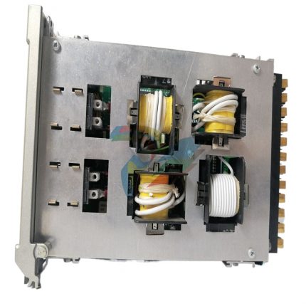
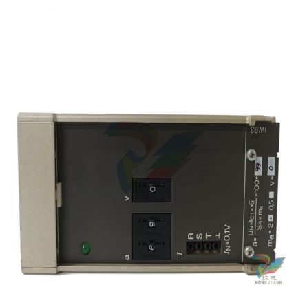
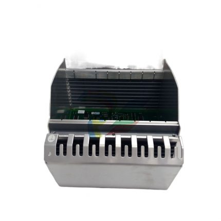
ABB PPC905AE101 3BHE014070R0101 control module
Original price was: $9,584.00.$9,056.00Current price is: $9,056.00.个
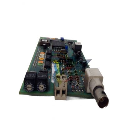
ABB XVC770BE101 3BHE02103R0101 circuit board module
Original price was: $8,606.00.$8,377.00Current price is: $8,377.00.个
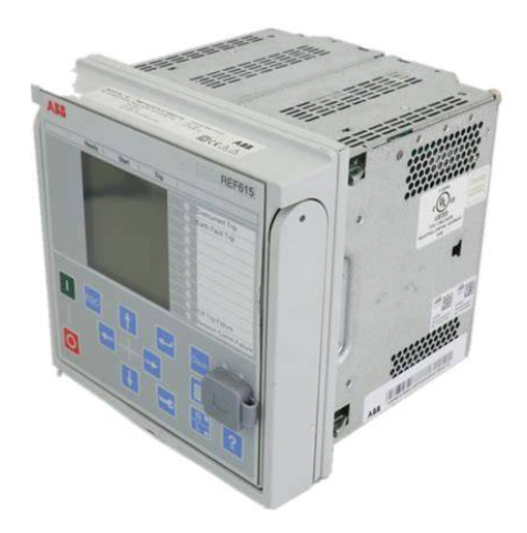
ABB REF615E_E HBFHAEAGNBA1BNN1XE digital feeder protection relay
Original price was: $14,833.00.$12,747.00Current price is: $12,747.00.个
ABB REF615E_E (order number: HBFHAEAGNBA1BNN1XE) is a high-precision digital protection relay designed for feeder circuits in medium and low voltage distribution networks, belonging to ABB RELION ® 615 series core protection device. As the core equipment for feeder protection in distribution networks, its core function is to monitor the electrical quantities such as current, voltage, and power of feeder circuits in real time, accurately identify fault types such as short circuits, overloads, grounding faults, overvoltages, and undervoltages, and cut off faults through fast and reliable protection actions. At the same time, it has telemetry, remote signaling, and remote control (three remote) functions to achieve comprehensive monitoring and lean management of feeder circuits.
Description
ABB REF615E_E HBFHAEAGNBA1BNN1XE digital feeder protection relay
Product Overview
ABB REF615E_E (order number: HBFHAEAGNBA1BNN1XE) is a high-precision digital protection relay designed for feeder circuits in medium and low voltage distribution networks, belonging to ABB RELION ® 615 series core protection device. As the core equipment for feeder protection in distribution networks, its core function is to monitor the electrical quantities such as current, voltage, and power of feeder circuits in real time, accurately identify fault types such as short circuits, overloads, grounding faults, overvoltages, and undervoltages, and cut off faults through fast and reliable protection actions. At the same time, it has telemetry, remote signaling, and remote control (three remote) functions to achieve comprehensive monitoring and lean management of feeder circuits.
This relay integrates ABB’s advanced algorithms and digital technology in the field of power system protection, using a 32-bit high-performance microprocessor and modular hardware architecture. It has the characteristics of flexible configuration of protection logic, fast action speed, high measurement accuracy, strong anti-interference ability, and rich communication interfaces. It is widely used in 10kV and below feeder circuit protection in substations, industrial enterprise distribution stations, commercial complex distribution rooms and other scenarios, and is a key component in building an intelligent distribution network protection system.
Core functions and protective features
1. Core protection function
-Short circuit and overload protection: Built in three-stage overcurrent protection (quick break, limited time quick break, overcurrent) and inverse time overcurrent protection functions, which can flexibly configure protection settings according to the load characteristics of the feeder. Quick break protection action time ≤ 20ms, capable of quickly cutting off serious short-circuit faults; The inverse time protection can automatically adjust the action time according to the magnitude of the fault current, adapt to the protection coordination requirements of different capacity feeders, and avoid the expansion of faults.
-Grounding fault protection: Supports two grounding fault detection modes: residual current protection and zero sequence current protection. For small current grounding systems (neutral point not grounded or grounded through arc suppression coils), the fifth harmonic braking or line selection algorithm is used to accurately identify single-phase grounding faults with an action sensitivity of ≤ 30mA, effectively solving the problem of grounding fault location in distribution networks.
-Voltage protection function: integrates overvoltage protection, undervoltage protection, and voltage imbalance protection functions. When the feeder voltage exceeds the set value (the overvoltage set value can be set to 1.05-1.2 times the rated voltage, and the undervoltage can be set to 0.7-0.95 times the rated voltage), an alarm or trip command is quickly issued to prevent voltage abnormalities from causing damage to downstream electrical equipment.
-Special protection and interlocking function: equipped with reclosing function (single-sided power supply/double-sided power supply optional), supporting pre reclosing acceleration and post reclosing acceleration logic, improving the reliability of power supply in the distribution network; Simultaneously supporting auxiliary protection functions such as low cycle load shedding, overload alarm, CT disconnection detection, etc., interlocking control with circuit breakers and isolating switches can be achieved through logic programming.
2. Additional practical features
-High precision measurement and data recording: With a power measurement accuracy of 0.2 level, it can collect and calculate real-time electrical parameters such as active power, reactive power, power factor, and power (forward/reverse) of the feeder line; Built in fault recording function, which can record the electrical waveform of 200ms before and 800ms after the fault, with a sampling rate of 1kHz, providing accurate data for fault analysis.
-Flexible communication and intelligent capabilities: Supports mainstream power communication protocols such as IEC 61850, Modbus TCP/RTU, DNP3.0, equipped with 2 Ethernet interfaces and 1 RS485 interface, seamlessly integrated into intelligent substation automation systems (SAS) or distribution network automation platforms, enabling remote uploading of protection information and measurement data and remote setting of settings.
-Custom Logic and Fixed Value Management: Provides graphical logic programming tools to support users in customizing protection logic and interlocking conditions based on actual needs; It has the function of storing multiple sets of fixed value groups (up to 8 sets), and can quickly switch between fixed value groups through communication or local operation, adapting to the protection needs of different operation modes of feeders (such as maintenance and normal power supply).
-High reliability and environmental adaptability: using industrial grade high stability components and passing IEC 61000 series electromagnetic compatibility testing, it can effectively resist surges, electromagnetic radiation, and high-frequency interference in the distribution network; The working temperature range is -40 ℃~+70 ℃, and the protection level is IP40. It can adapt to various installation environments such as outdoor terminal boxes and indoor control cabinets.
Key technical parameters
Power parameters
DC power supply: 24V DC/48V DC/110V DC/220V DC ± 20%; AC power supply: 110V AC/220V AC ± 20%; Power consumption: ≤ 15W
Adapt to commonly used AC/DC operating power sources in distribution networks, with strong voltage adaptability
Current input
Rated current: 5A or 1A (CT secondary side); Measurement range: 0.1In~20In; Current measurement accuracy: 0.2 level
Compatible with mainstream CT specifications for distribution networks, with high measurement accuracy
Voltage input
Rated voltage: 100V (line voltage)/57.7V (phase voltage); Measurement range: 0.1Un~1.2Un; Voltage measurement accuracy: 0.2 level
Adapt to PT secondary output voltage to meet voltage monitoring and protection requirements
Protection action time
Quick break protection: ≤ 20ms; overcurrent protection: adjustable (100ms~10s); Ground fault protection: ≤ 30ms
Quickly respond to faults and effectively limit the impact of faults
Output contact
Trip output: 4 pairs (normally open, capacity AC 250V/5A DC 220V/2A); Signal output: 6 pairs (normally open/normally closed optional)
Meet the driving requirements of trip circuit and signal circuit
communication interface
2 Gigabit Ethernet interfaces (supporting IEC 61850-9-2); 1 RS485 interface (supporting Modbus RTU)
Support seamless integration with automation systems to achieve remote monitoring
fault recording
Sampling rate: 1kHz; Record duration: 200ms before fault+800ms after fault; Storage capacity: ≥ 100 recorded waveform data
Provide complete data support for fault analysis
working environment
Temperature: -40 ℃~+70 ℃; Humidity: 5%~95% (no condensation); Protection level: IP40
Adapt to various outdoor and indoor installation environments, with strong environmental adaptability
Installation method
35mm standard DIN rail installation or panel embedded installation
Adapt to different cabinet structures and installation space requirements
Typical application scenarios
This digital feeder protection relay is widely used in distribution networks and industrial fields due to its precise protection performance, rich functional configuration, and high reliability. Typical scenarios include:
1. Public substation feeder protection: used for the outgoing feeder protection of 10kV/35kV public substations. As the main protection device of the feeder, it can quickly cut off short circuits, overloads, and grounding faults, improve the reliability of power supply in the distribution network with the help of reclosing function, and reduce the time of power outages for users.
2. Industrial enterprise distribution station: Used for the protection of workshop power feeders and motor feeders in self owned distribution stations of large industrial enterprises such as steel, chemical, and manufacturing industries. In response to the high impact of industrial loads, flexible configuration of protection settings is adopted to ensure the safety of production equipment and the continuity of power supply.
3. Commercial and Civil Distribution Network: Used for the protection of 10kV incoming and 0.4kV outgoing feeders in commercial complexes, residential areas, and data centers. Through overvoltage and undervoltage protection, sensitive electrical equipment such as air conditioners and servers are prevented from being damaged by abnormal voltage, ensuring the safety of commercial operations and residential electricity consumption.
4. New energy distribution network: In the protection of grid connected cables in distributed photovoltaic and wind power projects, it is used to protect the feeder lines connecting the new energy power station and the distribution network. It has anti islanding detection auxiliary function to ensure the safe grid connection of the new energy generation system and reliable disconnection from the grid in case of faults.
5. Railway and Rail Transit: Used for auxiliary feeder protection in distribution stations and traction substations along railways, adapting to the harsh electromagnetic environment and wide temperature working requirements of railway systems, ensuring stable power supply for key loads such as signal systems and lighting systems.
Installation and maintenance precautions
1. Installation specifications
-Relays should be installed in control rooms or protective screens with good ventilation, no severe vibration (vibration acceleration ≤ 3g), no corrosive gases, and no strong electromagnetic radiation. For outdoor installation, terminal boxes with a protection level of ≥ IP54 should be equipped; Reserve a heat dissipation space of ≥ 50mm around the relay to avoid direct proximity to heating elements (such as power modules).
-Strictly distinguish between current circuits, voltage circuits, power circuits, and communication circuits, and use cables of different colors for identification (such as yellow/green for current circuits, red for voltage circuits, and blue for communication circuits); The current circuit should use copper core cables (cross-sectional area ≥ 2.5mm ²), and the wiring should be firm to avoid open circuits on the CT secondary side.
-When connecting CT and PT, it is necessary to ensure that the polarity is correct and that the “·” end of the current circuit corresponds to the “L” end of the voltage circuit, in order to avoid protection misoperation or refusal due to wiring errors; Voltage circuits should be equipped with fuses (capacity 2A), while current circuits are strictly prohibited from installing fuses to prevent high voltage caused by CT open circuits.
-Relay grounding should comply with the grounding specifications of the power system, and the protective grounding should be reliably connected to the system grounding grid with a grounding resistance of ≤ 4 Ω; The communication cable adopts shielded twisted pair, with the shielding layer grounded at one end to reduce signal transmission interference.
2. Maintenance points
-During daily inspections, check the operating status (current, voltage, power, set value group) and alarm information through the relay LCD screen, and confirm that the indicator light status is normal (power light is always on, running light is flashing, and there are no fault light alarms); Regularly verify the consistency between measurement data and on-site instruments through the upper system.
-Clean and maintain the relay every quarter, using compressed air or dry soft cloth to clean the dust on the surface of the relay and the wiring terminals. Check whether the wiring terminals are loose, especially the current and voltage circuit terminals. If loose, tighten them in a timely manner (copper core cable torque value: 2.5mm ² is 1.2N · m).
-Conduct protection setting verification and functional testing every six months, simulate short-circuit, overload, grounding faults and other working conditions through relay protection testers, and verify the accuracy and action time of protection actions; Before testing, it is necessary to exit the trip outlet pressure plate to avoid accidental tripping.
-Regularly check the stability of the communication link, check the communication status through the upper system, and ensure normal data transmission; Export fault recording data and operation logs annually, clean up expired data, and ensure sufficient storage space.
-When a relay malfunctions, the relevant protective pressure plate should be immediately removed, and the cause of the fault should be preliminarily identified through the fault code and waveform data; When replacing the relay, it is necessary to ensure that the new equipment model is consistent with the order number. After replacement, it should be reconfigured and functionally tested. Only after passing the test can it be put into operation.
Additional information
| Dimensions | 738 × 673 × 583 in |
|---|
Reviews (0)
Shipping and Delivery


Reviews
There are no reviews yet.