
-6%

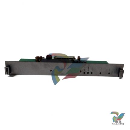
ABB A30-30-10RT three pole AC contactor
Original price was: $37,273.00.$33,737.00Current price is: $33,737.00.个
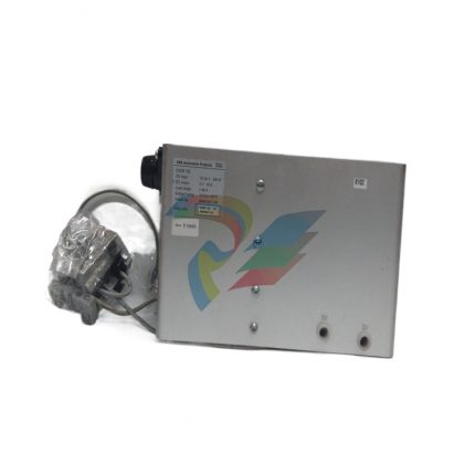
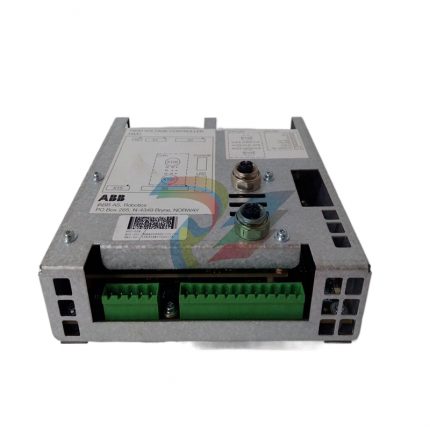
ABB NBIO-31 3BSE011337R1 I/O and Expansion Control Module
Original price was: $7,375.00.$6,836.00Current price is: $6,836.00.个
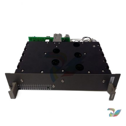
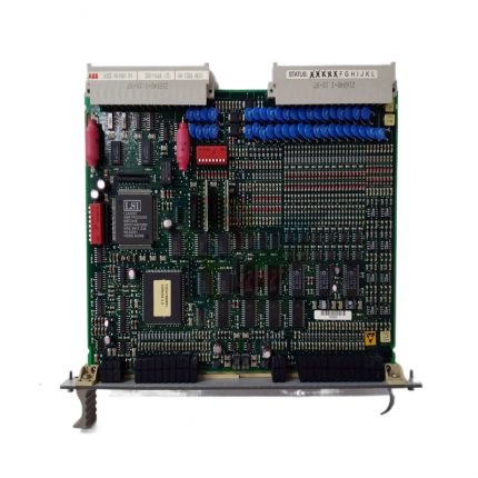
ABB SYN5302A-Z, V217 3BHB006716R0217 digital synchronizer
Original price was: $28,458.00.$26,884.00Current price is: $26,884.00.个
The core function of a digital synchronizer is to solve the problem of “multi-source power collaboration” – when multiple devices are running together, real-time monitoring and adjustment are used to ensure that key parameters such as output frequency, voltage phase, and speed of each unit remain consistent, avoiding equipment impact, power oscillation, and even system collapse caused by parameter deviations. SYN5302A-Z, V217, as a product designed by ABB specifically for medium and high voltage industrial scenarios, is positioned as a “high-precision synchronous control center”. It connects to the status sensors of on-site equipment (such as speed sensors and voltage transformers) and interfaces with the PLC or DCS main control system, forming a closed-loop control of “monitoring calculation regulation”.
Description
ABB SYN5302A-Z, V217 3BHB006716R0217 digital synchronizer
Product core positioning and application scenarios
The core function of a digital synchronizer is to solve the problem of “multi-source power collaboration” – when multiple devices are running together, real-time monitoring and adjustment are used to ensure that key parameters such as output frequency, voltage phase, and speed of each unit remain consistent, avoiding equipment impact, power oscillation, and even system collapse caused by parameter deviations. SYN5302A-Z, V217, as a product designed by ABB specifically for medium and high voltage industrial scenarios, is positioned as a “high-precision synchronous control center”. It connects to the status sensors of on-site equipment (such as speed sensors and voltage transformers) and interfaces with the PLC or DCS main control system, forming a closed-loop control of “monitoring calculation regulation”.
Typical application scenarios can be divided into three categories:
-Parallel control of power generation system: In thermal power plants and hydropower stations, achieve “quasi synchronous” grid connection between multiple generator units and the power grid – accurately adjust the speed and voltage of the units to be connected to the grid, so that the frequency, phase, and voltage amplitude of the units and the power grid are completely matched to complete the grid connection operation, avoiding large current surges at the moment of grid connection; Maintain power balance distribution among multiple generators in islanded power supply scenarios.
-Industrial drive synchronous control: In the cold/hot rolling production line of the metallurgical industry, the speed synchronization of multiple roller conveyor motors is controlled to ensure that there is no stretching or wrinkling during the steel plate transportation process; The paper winding machine and unwinding machine in the papermaking industry achieve stable control of paper tension through speed synchronization.
-Ship and Ocean Engineering: When multiple diesel generators of large ships operate in parallel, stable coordination of the power system is achieved through synchronizers; In the emergency power supply system of the offshore platform, ensure that the backup generator can quickly switch synchronously with the main power grid.
Core functions and technological advantages
1. High precision digital synchronous detection and adjustment
The equipment adopts a 32-bit high-performance microprocessor and is equipped with ABB’s proprietary synchronization algorithm. It can collect multiple voltage (0-1000V AC) and speed (0-10000rpm) signals in real time, with a sampling frequency of up to 1kHz, frequency measurement accuracy of ± 0.001Hz, and phase measurement accuracy of ± 0.1 °. For different working conditions, there are two built-in control modes: “quasi synchronization” and “self synchronization”. The quasi synchronization mode achieves impulse free grid connection by finely adjusting the speed and voltage; The self synchronization mode is suitable for emergency situations, quickly pulling the unit into synchronization and enhancing the system’s emergency response capability.
2. Multi source signal compatibility and adaptive adjustment
Supports multiple types of input signals, including reluctance speed sensor signals (0-10V DC), voltage transformer signals (100V/57.7V AC), encoder signals (TTL level), and can be directly connected to different brands of field devices without the need for additional signal conversion modules. At the same time, it has adaptive adjustment function, which can dynamically adjust the synchronization parameters according to load changes (such as power grid load fluctuations, sudden changes in rolling mill load), ensuring that the synchronization accuracy is maintained even in case of sudden changes in working conditions, and avoiding parameter overshoot or loss of step.
3. Comprehensive safety protection and fault diagnosis
Built in multiple safety mechanisms, including overvoltage protection (automatically cutting off signal circuit when input voltage exceeds 1200V AC), overcurrent protection, demagnetization protection, and frequency anomaly protection (triggering alarm when frequency exceeds the range of 45-55Hz). The equipment has comprehensive fault diagnosis functions, which can monitor its own hardware status (such as power supply, sampling circuit) and external signal quality in real time. It outputs fault codes (such as “signal loss”, “synchronization timeout”, “hardware failure”) through LED indicator lights and RS485 communication interface, making it easy for operation and maintenance personnel to quickly locate problems.
4. Flexible communication and integration capabilities
Equipped with RS485 and Modbus RTU communication interfaces, it can seamlessly integrate with mainstream PLCs such as ABB AC 800M and S7-1200, as well as monitoring systems such as WinCC and Intouch. It supports uploading synchronization status, operating parameters, and fault information, while receiving control commands from the upper computer (such as “start synchronization” and “stop grid connection”). The device supports local configuration of parameters (via front panel buttons) and remote configuration (via communication interface) to meet the needs of different operation and maintenance scenarios.
5. Industrial grade stability and environmental adaptability
Adopting a fully metal casing and modular design, the internal circuit has been optimized for EMC (electromagnetic compatibility) and meets the IEC 61000-4 standard, which can resist electromagnetic interference and voltage fluctuations in industrial sites. The working temperature range is wide to -10 ℃~70 ℃, and the humidity adaptation range is 0~95% (no condensation). It can operate stably in high temperature, high humidity, and dusty industrial environments, with a protection level of IP40 (panel)/IP20 (backboard).
Key technical parameters
Basic Information
Model/Order Number
SYN5302A-Z,V217 / 3BHB006716R0217
Power parameters
Working Voltage
24V DC (± 20% fluctuation range), optional 110/220V AC/DC
Power consumption
Typical value ≤ 15W, maximum power consumption ≤ 20W
input signal
voltage signal
Input range: 0-1000V AC, frequency: 50/60Hz (adaptive)
speed signal
Supports magneto resistive sensors (0-10V DC) and encoders (500-1024 wires)
Signal accuracy
Frequency measurement accuracy ± 0.001Hz, phase measurement accuracy ± 0.1 °
output signal
controlled output
4-20mA analog output (used to adjust speed/voltage), 2-channel relay output (grid connection allowed/fault)
communication interface
RS485, Supports Modbus RTU protocol, communication speed 9600-115200bps
Environment and Structure
working environment
Temperature: -10 ℃~70 ℃, humidity: 0~95% (no condensation)
Protection level
Panel IP40, Backboard IP20
Overall dimensions
48mm x 177mm x 150mm (width x height x depth, standard 19 inch rack installation)
control mode
synchronous mode
Quasi synchronous and self synchronous (can be manually switched)
Key points of installation and integration
1. Installation specifications
The equipment is installed on a standard 19 inch rack, with a reserved installation depth of ≥ 200mm (for easy wiring and heat dissipation). The installation location should be far away from strong magnetic field equipment (such as large transformers, frequency converters) and high-temperature heat sources (such as exhaust vents of cooling fans) to avoid signal interference and equipment overheating. When wiring, it is necessary to strictly distinguish between the “power circuit”, “signal input circuit”, and “control output circuit”. The cables of the three circuits should be laid separately, and it is recommended to use shielded twisted pair cables for signal cables. The shielding layer should be grounded at one end (grounding resistance ≤ 4 Ω) to prevent electromagnetic interference.
2. System integration steps
1. Hardware connection: Connect the voltage transformer signal to the “voltage input” terminal, the speed sensor signal to the “speed input” terminal, the 4-20mA adjustment signal to the “control output” terminal, connect to the upper controller through RS485 cable, and finally connect to the working power supply (pay attention to positive and negative polarity).
2. Parameter configuration: Configure basic parameters through the “function keys+display screen” on the front panel of the device – set the rated frequency (50/60Hz), voltage level (such as the transformer ratio corresponding to 10kV/6kV), synchronization allowable deviation (such as frequency deviation ≤ 0.1Hz, phase deviation ≤ 5 °), and communication parameters (baud rate, address).
3. Linkage debugging: Configure communication links in the upper computer monitoring system to ensure real-time reading of parameters such as “current frequency”, “phase difference”, and “synchronization status” of the synchronizer; Simulate the synchronization scenario (such as adjusting the generator speed), test whether the synchronizer can accurately issue adjustment commands, and verify whether the “synchronization completion” signal is triggered normally.
4. Fault testing: Artificially simulate faults such as signal loss and frequency abnormality, check whether the synchronizer can trigger an alarm in a timely manner and output a fault code, and verify whether the protection mechanism is effective (such as cutting off the grid connection permission signal).
Common faults and troubleshooting methods
Fault phenomenon
Possible reasons
Troubleshooting method
The power indicator light is not on, and the device is unresponsive
Power supply not connected, power cord loose, power module malfunction
Measure the voltage of the power input terminal with a multimeter to see if it is normal; Re plug and unplug the power cord and tighten the terminals; Replace the backup power supply for testing. If there is still no response, the power module needs to be repaired.
The synchronization indicator light is flashing, unable to complete synchronization
Abnormal input signal, unreasonable synchronization parameter settings, and excessive load fluctuations
Check if the voltage/speed signal is normal (measure the signal waveform with an oscilloscope); Check if the synchronization allowable deviation parameter is too small (such as setting the frequency deviation to 0.01Hz, which makes it difficult to meet); Temporarily reduce the load and observe if the synchronization process is stable.
The upper computer cannot read device data
Loose communication cables, mismatched communication parameters, and communication interface failures
Check if the A/B wires of the RS485 cable are reversed; Check whether the baud rate, address, and protocol of the synchronizer are consistent with those of the upper computer; Use a serial debugging tool to test whether the communication interface can send and receive data normally, and eliminate software problems on the upper computer.
Trigger fault alarm after synchronization is completed
Instantaneous surge current during grid connection is too high, and overvoltage protection parameters are set too low
Measure the peak current/voltage at the moment of grid connection and confirm whether it exceeds the protection threshold; Adjust the triggering threshold of overvoltage and overcurrent protection appropriately (within a safe range); Check the synchronization accuracy to ensure that the phase difference is indeed within the allowable range during grid connection.
Additional information
| Weight | 4.83 lbs |
|---|---|
| Dimensions | 454 × 573 × 447 in |
Reviews (0)
Shipping and Delivery


Reviews
There are no reviews yet.