GE Multilin MM2 Motor Manager 2 Manual
The official operation manual of GE Multilin MM2 Motor Manager 2 (firmware/software V5.2x) is a low-voltage motor integrated protection and control device, which integrates a complete set of motor protection such as three-phase overload, locked rotor, ground fault, under/over voltage, thermistor, etc. It supports 13 types of starter control, RS485 Modbus RTU communication, and panel/remote/software triple operation. Parameter configuration, real-time monitoring, fault diagnosis, and maintenance statistics are achieved through the front panel keyboard+LED+20 × 2 display screen. It is suitable for MCC motor control centers and has industrial grade features such as expandable I/O, programmable logic, under voltage self start, and user-defined memory mapping, meeting the needs of motor safe operation and intelligent monitoring.
Product basic information
MM2 (Motor Manager 2) is a low-voltage motor comprehensive protection controller launched by GE Multilin, used in MCC motor control centers to achieve integrated protection, control, monitoring, and communication.
Firmware/Software Version: V5.2x
Manual Number: 1601-0056-DU (GEK-106294F)
Power supply: 120/240V AC, 50/60Hz
Installation: Panel installation (with display), rack installation (black box type)
Certification: UL, CE, ISO9001:2000
Environment: 0-60 ℃, IP53,NEMA 12
Hardware structure
1. Front panel
Display: 20 × 2 character LCD
LED: operation, shutdown, tripping, alarm, fault, contactor A/B, auxiliary relay, automatic/manual
Keys: Set value, actual value, store, stop, reset, start A/B, message/numerical value up, down, left, right
2. Input/output interface
Type and specification
Current input three-phase CT (1A/5A), grounding CT (5A/50:0.25)
Voltage input VT input 120V AC, maximum 600V
Switch input 120V AC optocoupler isolation, up to 10 programmable channels
Analog input 4-20mA, accuracy ± 1% FS
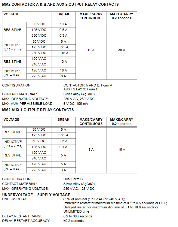
Relay output contactor A/B, auxiliary 1/2, contact capacity 10A/240V AC
RS485 communication, 2-wire half duplex, Modbus RTU
3. Core hardware
Main CPU: 16 bit 68HC16, 16MHz
Backup CPU: 68HC705, power-off timer ≥ 1 hour
Sampling: 1.67ms true RMS
Storage: EEPROM saves parameters, not lost in case of power failure
Protection function (S2 configuration)
Covering all types of motor faults, with high accuracy and precise action time
thermal overload protection
Curve: 8 standards+4 NEMA CLASS (10/15/20/30)
Accuracy: ± 200ms (≤ 10s), ± 2% (>10s)
Thermal model: Cold to heat ratio of 20% to 100%, shutdown cooling time of 5 to 1080 minutes
Ground fault protection
Detection: Residual/Zero Sequence CT, 50:0.025 High Sensitivity Type
Threshold: 0.1~15A or 3%~100% CT
Action delay: 0-10s (set separately for startup/operation)
locked-rotor protection
Threshold: 1.15~4.50 × FLC
Delay: 0.5~5s
Other protections
Phase failure/imbalance:>30% imbalance, 5-second action
Under/Over Voltage: 0~600V, Delay of 1~60s
Underload/underpower: 10%~100% FLC, delay of 1-60s
Thermistor: PTC/NTC, 100~30000 Ω
Control function (S1/S4 configuration)
Supports 13 types of initiators
Full voltage irreversible/reversible, dual speed, star delta (open/closed loop), autotransformer, wound rotor, series resistor, frequency converter, soft start, backup interlock
control mode
Two line/three line, manual/automatic, local/remote, interlock control
Under voltage self starting
Instant restart: 100~500ms
Delayed restart: 0.2~30s
Power down memory time: up to 1 hour
Programmable input
10 configurable channels: interlocking, lock reset, automatic permission, testing, remote permission, etc
Monitoring and Maintenance (S5/A Real Value)
real-time data
Three phase current, grounding current, voltage, power, load rate, thermal capacity, imbalance
statistical data
Duration of operation/shutdown, number of starts, various trip counts, interlock counts
Maintenance reminder
Motor lubrication interval: 100~50000h
Contactor inspection: 1000~1000000 times
Maximum shutdown alarm: 10-10000 hours
Communication (Modbus RTU)
electrical interface
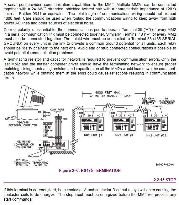
RS485, 2-wire half duplex, up to 4000 feet long, up to 32 units
Baud rate: 1200/2400/4800/9600/19200
Support function code
01H: Reading coil
03H/04H: Read Register
05H: Execute Command
06H: Write a single set value
10H: Write multiple set values
memory mapping
Real value range: 0000~0FFF
Set value area: 1000~1FFF
User defined area: 0100~0177, 1280~12F7
Installation and Testing
Install
Panel opening: 7.50 × 7.10in (191 × 180mm)
Wiring: CT strictly prohibits open circuit, communication shielding is grounded, terminal resistance is 120 Ω
test
First/Second Injection Test
Current, imbalance, grounding, thermal sensitivity, and power failure tests
Control wiring
Two wire/three wire, manual/automatic/interlocking, emergency stop
Software Tool (MM2PC)
Function: Parameter reading and writing, configuration saving, firmware upgrade, real-time monitoring
Connection: RS232/485 converter
Applicable to: Windows system, provided for free
Key issues
Question 1: What are the core advantages of MM2 compared to traditional motor relays?
Answer: The core advantage is integrated protection, which combines overload, grounding, locked rotor, undervoltage, thermal sensing, imbalance and other full protection, 13 starter controls, real-time monitoring, and Modbus communication into one device; Supports programmable I/O, under voltage self start, power-off thermal memory, user-defined memory, higher accuracy (RMS sampling), more comprehensive protection, remote monitoring, significantly reducing MCC wiring and maintenance costs.
Question 2: What are the two connection methods for ground fault protection of MM2 and what scenarios are they applicable to?
answer:
5A secondary CT/residual connection method: suitable for conventional grounding systems, sensitivity 5% motor CT, low cost, strong universality.
50:0.025 High sensitivity zero sequence CT: suitable for high resistance grounding systems, can detect 0.1A level low current grounding, provide early insulation warning, and avoid false tripping.
Question 3: How many Modbus communication devices can be connected to MM2 at most? What core operations are supported and how can communication stability be ensured?
answer:
Up to 32 devices can be connected via daisy chain, with a communication distance of 4000 feet.
Core operations: read and write set values, read real values, remote start stop, reset trip, circuit testing.
Stability measures: Shielded wire single ended grounding, terminal 120 Ω resistor+1nF capacitor, correct polarity, avoid star wiring, baud rate matching.