Pro face GP2400/2500/2600 series programmable human-machine interface (HMI)
The official user manual for the Pro face GP2400/2500/2600 series programmable human-machine interface (HMI) is designed for industrial automation scenarios. It comes with three standard features: Ethernet, CF card, and audio output, and is compatible with Pro Designer software. It covers the entire process of safety specifications, model specifications, installation and wiring, system settings, troubleshooting, and maintenance. It supports DC24V/AC100~240V dual power supply, RS-232C/RS-422/Ethernet communication, TFT color/monochrome LCD, 50000 hour backlight, IP65 front panel protection, and is compatible with mainstream PLCs such as Mitsubishi. It is suitable for equipment monitoring and operation control.
Product Fundamentals and Models
GP2400/2500/2600 is an embedded HMI launched by Pro face, which can achieve Ethernet, CF card, and sound output without the need for expansion modules.
Applicable software: Pro Designer Ver. 4.0 and above
Typical model:
GP2400-TC41-24V
GP2500-LG41-24V (monochrome), SC41-24V (STN color) TC41-24V(TFT)
GP2600-TC41-24V
Core technical specifications
1. Electrical specifications
Type parameter
Power supply DC24V (19.2~28.8V); AC100~240V(85~265V)
Power consumption: DC type ≤ 28~50W; AC type ≤ 50~85VA
Insulation AC1000V/1500V for 1 minute, insulation resistance ≥ 10M Ω
Maintain lithium battery backup SRAM in case of power failure, clock accuracy ± 65 seconds/month
2. Display and Touch
Project parameters
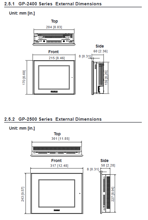
Resolution 2400/2500: 640 × 480; 2600:800×600
256 colors/64 colors flicker; Monochrome is black and white
Touch analog resistive, 32 × 24 or 40 × 30 dot matrix
Backlight lifespan of 50000 hours (continuous operation at 25 ℃)
3. Interfaces and peripherals
COM1:RS-232C/RS-422,2400~115.2kbps
COM2: RS-232C, D-Sub9 pin
Ethernet: 10BASE-T, IEEE802.3
CF card: Supports 16MB/32MB for data storage and program startup
Audio: 70mW mono, Line Out 2.7Vp-p
Installation and wiring specifications
Installation requirements
Embedded panel installation, panel thickness 1.6~10mm
Reserved ventilation spacing of * * ≥ 100mm * * around the perimeter
Tilt installation angle * * ≤ 30 ° * *, cooling is required if it exceeds 30 °
Wiring safety
The power must be disconnected for wiring, and live plugging and unplugging are strictly prohibited
Grounding: Independent grounding priority, grounding resistance * * ≤ 100 Ω * *, wire diameter ≥ 2mm ²
The power circuit needs to be equipped with a circuit breaker, and this machine does not have a power switch
CF card usage
It must be plugged in and unplugged after the power/ACCESS light is turned off
Power off is prohibited during reading and writing, and data is backed up regularly
System settings
Divided into two categories: offline settings and system settings:
Offline settings
Network: Configure IP/Subnet Mask/Gateway
Buzzer: Off/Touch Response/Full Screen Response
Backlight: 4 brightness levels, automatic extinguishing, burn protection
Self check: screen, font, touch, serial port, video memory
System Settings
Date and time, language, version information
Memory usage viewing, system restart
Fault diagnosis
1. No display troubleshooting
Check if the power supply voltage is within the rated range
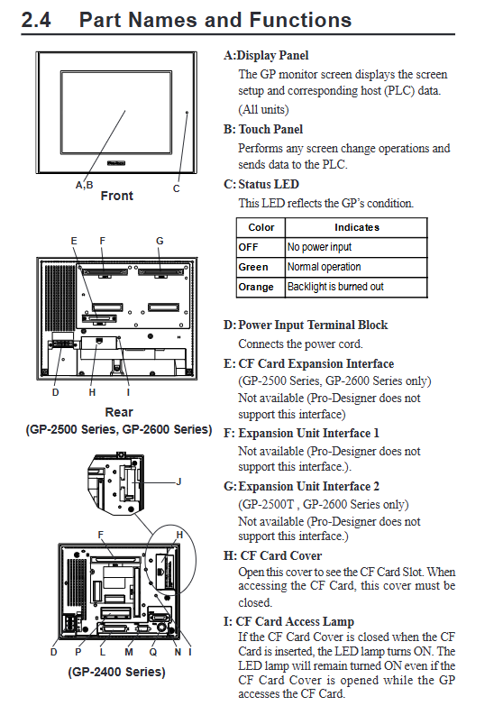
Confirm LED status: green=normal, orange=backlight damaged
Check if the Pro Designer screen is downloaded correctly
Check if the power terminal wiring is secure
2. Troubleshooting of communication abnormalities
Confirm that the PLC protocol and driver settings are correct
Check the communication line wiring and shielding grounding
Verify that the baud rate, data bits, and parity bits are consistent
Maintenance and upkeep
Daily cleaning
Neutral cleaning agent soft cloth wiping, organic solvents are prohibited
regular replacement
Install gasket: replace annually
Backlight: Replace when the LED is orange, match the model with the model
Lithium battery
Used for clock and data backup, cannot be replaced by oneself, please contact the agent
Key issues
Question 1: Why is it strictly prohibited to use touch screens as emergency stop buttons for GP2000 series HMI? What are the security risks?
Answer: The touch screen belongs to software control and may maintain or fail signals due to communication failures, crashes, black screens, or program errors; And emergency stop involves personal safety, and the hardware emergency stop button must be used to directly cut off the circuit. If a soft button is used, failure to stop the machine in a timely manner may result in personal injury or equipment damage.
Question 2: What is the correct process for inserting and removing CF cards? What are the consequences of violating regulations?
Answer: Correct process: First, turn off the CF card access switch → Confirm that the ACCESS light is off → Open the cover and plug it in → Close the cover after plugging it in → Power on for use. Violation consequences: Inserting or unplugging during read/write operations can result in data damage to the CF card, file loss, burning of the HMI storage chip, and inability to recover data.
Question 3: After the backlight is turned off, the HMI touch screen can still be operated. What are the hidden dangers? How to avoid it?
Answer: Hidden danger: If the operator cannot see the screen but the touch still takes effect, it is easy to accidentally touch the button or operate the equipment, causing safety accidents. Avoidance method: Enable the * * “Do not touch after backlight burn out” * * function in offline settings. When the backlight is damaged, the touch will be automatically locked and forced to repair before operation.