Honeywell 7800 Series EC/RM7830A/7850A Combustion Relay Module
Product positioning and model differentiation
The 7800 series is a Honeywell microprocessor based integrated combustion safety controller used for automatic ignition and safe shut-off of single burners.
Model control type applicable to burner
EC/RM7830A ON/OFF switch type ignition/shutdown two-stage type
EC/RM7850A Full Modulation Continuous Modulation High Fire/Low Fire Proportional Adjustment
Common functions:
Automatic combustion timing control
Flame signal monitoring
System status indication
Self diagnosis and fault locking
Multilingual display (English/Spanish/French/German/Italian/Japanese)
Security and Certification
Safety level: SIL 3
EU standards: EN298, EN60730, EMC, Low Voltage Directive
International certifications: FM, Lloyd’s, GASTEC
Protection type: Stop Category 0 Immediate power off
Electrical specifications
Project parameters
RM version 120 Vac (+10/-15%), 50/60Hz
EC version 220/240 Vac (+10/-15%), 50/60Hz
Maximum power consumption of 10W
The maximum total load is 2000 VA
Insurance 15A rapid melting SC type
Working temperature -40 ° C~+60 ° C
Humidity 85% RH non condensing
Hardware structure
Core Unit
Microprocessor controller
Safety relay (dual redundant)
Relay feedback monitoring
Pluggable component
Flame amplifier (R7847/7848/7849/7861/7886)
Purging time card (2s~30min)
Configure jumper wires
external extension
KDM keyboard display module
RS485/ModBus
remote reset
PC monitoring software
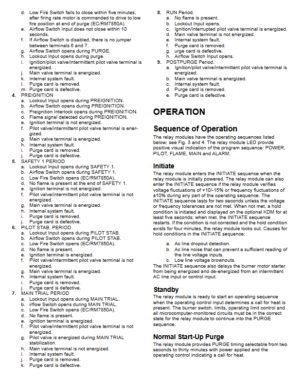
Terminal definition (core output)
1) EC/RM7830A key terminal
3: AL alarm
4: FAN fan
8: PV1 small fire valve
9: MV main fire valve
10: IGN ignition
17: ES2 pre ignition interlock
20: LOS lock input
21: PV2 auxiliary small fire
2) EC/RM7850A adds modulation terminal
12: Hi High Fire
13: COM Public
14: MOD modulation
15: LO low fire
18: ES1 low flame switch
19: ES3 high flame switch
Installation specifications
Installation location
Vertical installation priority
Anti vibration<0.5G
Moisture proof, not exposed to the outdoors
Mandatory wiring requirements
High voltage ignition wires must not be in the same tube as signal wires
Flame detector cable metal shielding
Strong electricity complies with NEC Class 1
cable specification
Strong current: 14-18 AWG
Signal/Communication: 22 AWG twisted pair shielded
Maximum line length
Remote reset: 1000ft (305m)
Communication bus: 4000ft (1219m)
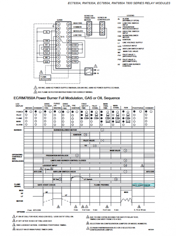
Combustion operation timing (fully automatic)
Initialize Initialization: 2s power self-test
Standby STANDBY: Waiting for heating request
Pre blowing PREPURGE: Fan start, air blowing
Pre ignition: Igniter power supply for 3 seconds
First safe time SAFETY 1:3/5s to establish flame
Small Fire Stable PILOT TAB.: 5s
Main Trial: 3/5s
Run: Normal combustion
Post blow POSTPURGE: 2/15/30s
Jumper configuration (key safety parameters)
Jumper function complete (uncut), cut off
JR1 first safety time 5s 3s
JR2 main fire test time 5s 3s
JR3 air volume switch is missing
Important rule: Change jumper after 200 hours of operation → permanently lock (Code110).
Static testing (mandatory for installation)
A total of 10-14 power-off/power on tests were conducted to verify:
Power supply, interlocking, alarm
Fan, ignition, small fire, main fire
Modulation motor (7850A)
Air volume switch, high and low fire limit
The fuel manual valve must be closed during testing to prevent explosion.
LOCKOUT trigger condition
No flame, flame loss
Pre blowing without air volume
Ignition timeout, valve not functioning
Missing/faulty blowing card
Change the jumper after 200 hours
Internal malfunction, abnormal power supply
Incorrect output during standby mode
Key issues
Question 1: What is the core difference between EC7830A and RM7830A? What is the core difference between 7830A and 7850A?
answer:
EC and RM: voltage difference; RM=120VAC,EC=220/240VAC。
7830A and 7850A: Different control methods; 7830A=ON/OFF, 7850A=Continuous Proportional Modulation (HI/LO/MOD).
Question 2: Why can’t the jumper be cut after the device has been running for 200 hours? What will happen? How to recover?
answer:
To prevent unauthorized modification of key parameters such as safety time/air volume switch on site.
Changing the jumper will trigger Code110 to permanently lock and cannot be reset.
Cannot be restored, the controller must be replaced.
Question 3: What is the function of pre blowing during burner start-up? What should be done if the air volume switch is missing?
answer:
Pre blowing exhausts residual combustible gases from the furnace to prevent detonation.
When there is no wind switch: keep the JR3 jumper and short-circuit terminals 6-7.
When there is an air volume switch: cut off JR3 and strictly prohibit 6-7 short circuiting, otherwise it will be locked.