CKD AxTools servo debugging software (EboDEX)
CKD AxTools Ver2.30 Windows version debugging software manual, specifically designed for TS/TH/MU/XS ABS ODEX servo drives, providing complete functions such as RS-232C communication connection, AI automatic gain/filter tuning, NC/G/M code programming, I/O/speed/FFT waveform monitoring, parameter reading and writing, and driver initialization. It supports automatic/manual/semi-automatic three-level debugging, built-in low-pass/notch filtering to suppress resonance, and meets motion control requirements such as positioning, continuous rotation, and segmented operation. All operations have clear safety warnings and step constraints.
Interface structure
Core functions of tab pages
Home file management, window switching, quick jump tuning/editing/monitoring
Set communication port, fieldbus, language, and driver information reading
Tuning servo gain, filtering adjustment, AI automatic tuning, test run
Edit NC/table program, parameters, point table, origin offset editing
Monitor I/O status, speed waveform, FFT resonance analysis
Detailed explanation of core functions
1. Communication and Basic Settings (Set Page)
Port settings: Select COM port → Connect/Disconnect
Device recognition: automatically reads model, serial number, firmware version, bus type
Language switching: Supports English/Japanese, takes effect upon restart
Security constraint: It is strictly prohibited to plug or unplug cables or turn on/off the device during communication
2. Servo tuning (Tuning page)
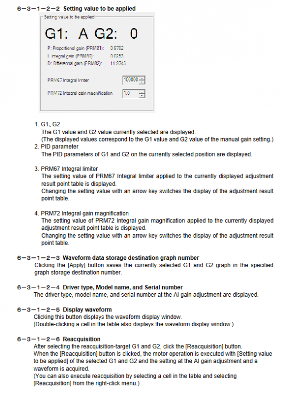
AI automatic gain: automatically scans G1/G2 combinations to generate the optimal PID
Movement angle: 1~360 °, time: 0.01~9s
Manual gain: P/I/D three loop adjustment, PRM80/81/82 parameters
Filtering system:
Low pass filtering 1/2:10~1000Hz
Notch filtering 1/2:10~1000Hz
Q value: 0.1~9.9 (narrowband=high Q)
Semi automatic tuning: only supports TS/MU/XS, automatic tuning needs to be completed first
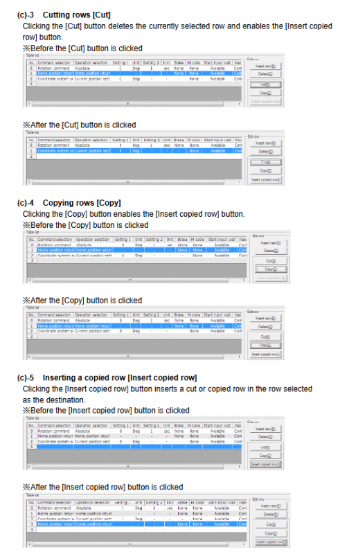
3. Program Editing (Edit Page)
Programming method:
NC code: N/G/M/A/F/P instructions
Divide and segment program: segment number 1-255, time 0.01-100s
Table program: Visual point table editing
Instruction core:
G-code: Positioning (G01), Zeroing (G28), Absolute (G90)/Incremental (G91)
M code: Stop (M00), End (M30), Brake (M68/M69)
Origin offset: supports manual offset or setting the current position to zero
4. Real time monitoring (Monitor page)
Axio: Monitor DI/DO status, waveform sampling up to 3000 points
AxSpeed: speed/position waveform, dual waveform comparison
AxFFT: Frequency analysis, resonance point detection, and filtering suppression
5. Motion Control (Universal)
Servo On/Off: Enable/Disable servo power
Alarm Reset: Clear the alarm and enable servo linkage
Test Run: Block emergency stop/Servo On input, safety test
Initialization: Restore factory parameters (cautious operation)
Key parameter table
Filter parameters (PRM62~71)
Default parameter number function range
62 low-pass filter 1 10~1000Hz 200
63 low-pass filter 2 10~1000Hz 500
64 notch filter 1 10~1000Hz 500
65 notch filter 2 10~1000Hz 500
66 filter switch 0~15 1
70/71 notch Q value 0.1~9.9 1.0
range of motion
Project Scope Unit
Positioning angle ± 360.000 ° deg
Running speed 0.11~300 rpm
Pulse command ± 540672 pulse
Number of segments: 1-255 segments
Key issues
Question 1: What is the principle of AxTools’ AI Gain auto tuning? What safety precautions should be taken during the tuning process?
answer:
AI Gain automatically traverses the G1/G2 parameter combination, drives the motor to run, collects waveform scores, and automatically recommends the optimal PID parameters.
Safety precautions:
Confirm that there is no mechanical interference or personnel approaching moving parts before tuning
Communication must be stable, and power cannot be disconnected or unplugged midway
Tuning completed requires restarting the driver parameters to take effect
Question 2: What is the function of AxFFT? How to use it to quickly suppress mechanical resonance?
answer:
AxFFT is used for frequency response analysis to identify the resonant frequency of the load.
Inhibition steps:
Enter Monitor → AxFFT → Start Test Mode to collect resonance peaks
Record resonance frequency (e.g. 228Hz)
Set the notch filter to this frequency in the Filter Setting
Write the driver and retest to confirm that resonance is suppressed
Question 3: What are the three programming methods supported by the Edit page? What application scenarios are suitable for each?
answer:
NC code programming: flexible instruction control, suitable for complex trajectories, loops, and conditional jumps
Divide and segment program: run in equal parts according to angles, suitable for dividing discs and rotating workstations
Table program: Visual point table editing, suitable for point sequence and multi segment positioning